How To -- Install FXDF Console on FXDB
#1
 09-29-2010, 06:29 PM

Join Date: Sep 2006
Location: Las Vegas, NV
Posts: 113
Likes: 0
Received 0 Likes
on
0 Posts
Upgrading the FXDB console to the FXDC/F console (UPDATE - check post #9 of this thread for more finished pics!)
I had been debating how to move the FXDB keyswitch from the terribly inconvenient fork neck factory location to the top of the tank where God intended it to be.
I had seen some pretty slick installs from other forum members by either swapping in the FXDWG dash, or simply boring a hole in the FXDB dash, and installing the switch there. But I liked the bigger 5" speedo of the FXDC/F models, and decided to try upgrading the standard 4" console to an FXDF console which can accept the larger 5" speedo.
These instructions are for upgrading a 2010 FXDB. 2009 models should be the same, but 2008 and earlier may (or may not) be different.
WHAT YOU'll NEED
MAJOR COMPONENTS NEEDED (EST. PRICE):
67096-09 : SPEEDOMETER, MPH ($180)
71313-96A: IGNITION SWITCH ($75)
71211-04 : FXDF CONSOLE wTRIM ($95)
TRIM/SMALL PARTS NEEDED (EST. PRICE):
61250-06 : EXTENSION, CONSOLE, LEATHER ($35)
67190-89 : SEAL, SPEEDOMETER ($10)
67271-04A: CLAMP, SPEEDO ($5)
68113-99B: INDICATOR LIGHT ASBLY ($30)
69538-04A: BEZEL, INDICATOR LIGHT ($10)
71304-04 : IGN SWITCH LABEL ($14)
LOCAL : 8-32 x3/8" IGN SW SCREWS, 4 ($1)
LOCAL : 12AWG WIRE, STRANDED, 3FT ($3)
TOTAL FOR ALL BRAND NEW PARTS: $458.
(Est. prices are for brand-new parts from a forum HD vendor)
Buying all these items brand new can be expensive. However, I was able to get some good deals on a used console and speedo (the most expensive parts of this upgrade) here on the forum, so if you do some shopping for used parts, you can probably do the entire upgrade for $250 or less. Not bad considering the ignition switch alone is $75, and is probably the only part I would recommend buying new instead of used.
Notes:
* The 2009-2010 5" dyna speedo uses the same electrical connector and wiring scheme as the 2009-2010 4" speedo, and is a plug-and-play swap.
* When you buy the keyswitch, supply your original 4 digit key number, and they can match the new lock to your existing keys. After this upgrade, the original keyswitch will fucntion only as a fork lock.
* IMPORTANT: Note the mileage on the original speedo *before* you start. You will need this information later, and you can't get it once power is removed from the speedo. You are required by law to have the new speedo set to show the true mileage, or to add a label to the bike stating that the indicated mileage is not accurate, along with other info.
Instructions - Keyswitch relocation prep
1) Disconnect the battery (we're going to be cutting into power wires, and we don't want to short out anything)
2) Remove gas tank mounting bolts and move tank back about 3 inches to give a little working room. You do not have to disconnect any gas lines. Pull the plastic wire concealment panel out from under the frame under the gas tank to gain access to the ignition switch and wires.
3) Just under the frame neck, remove the small black plastic plug just UNDER the fork lock pin. Grab it with a pliers and just pull it straight out.
4) Peel back the glued-on printed metal ring surrounding the keyswitch.
5) You'll see a metal collar with holes in it surrounding the keyswitch. There is a special tool for removing this locking collar, but you don't need it. Get a sturdy pair of needlenose pliers, open them up wide and insert the tips into opposite holes in the locking collar. Twist the pliers CLOCKWISE (yes, clockwise!) to rotate the locking collar. It will rotate inwards into the frame, and when sufficiently rotated, it will allow the switch to slide towards the back of the bike, and out of the frame. Note: You dont actually have to remove the switch entirely - just move it out enough to be able to remove the 3-wire connector. After removal of the 3-wire connector, push the keyswitch back up into its original position and retighten the locking collar by rotating counter-clockwise. Reinstall the black plug under the fork lock pin.
EXTENDING THE IGNITION WIRES
6) In order for the ignition wires to reach the new keyswitch position on the tank, you'll need to cut and extend each of the 3 wires from the connector you just removed from the ignition approximately 8-12 inches. Two of the wires are 12AWG, and the third one is slightly lighter guage, but I had 12AWG wire available, so I used that on all three. These are very important wires that carry a good amount of current, so whatever method you choose to extend them, make sure the connections are VERY SOLID and well-insulated after you splice. I cut the original wires about 3 inches behind the connector, and soldered in a 12 inch extension for each one, followed up with shrink tubing and tape. Set it aside for now.
REMOVAL OF STOCK FXDB CONSOLE
7) Remove the three screws that hold the gas tank console in place. The two on top of the tank are easy, but for the third one at the aft end of the tank, you have to remove the seat to gain access.
8) Lift the FXDB console up, flip it over, and disconnect the speedo connector, the indicator lights module connector, and unscrew the rubber cover from the trip reset button. Remove the console from the bike.
SPLICING THE NEW INDICATOR LIGHTS
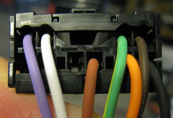
9) The new indicator light LED module from the FXDF uses a different connector that the one used by the FXDB. You will need to cut off the connectors, and splice each of the 7 wires from the FXDF indicator assembly onto the FXDB connector. It is rather tedious to do all 7, but the good thing is that the wire colors are coded the same, so all you have to do is match the colors up, do your solder/splice for each one, and you're good to go. (See wiring pics below)

MODIFICATION OF FXDB TANK BRACKET
The bracket attached to the tank top plate of the FXDB can be used to attach the FXDF console, but it needs to be slightly modified.
10) There are two 'ears' or brackets that stick up from the top plate of the gas tank. These need to be bent slightly to accomodate the wider width of the attachment points used by the FXDF console.
The attachement hole centers on the FXDF console are 4-1/4" appart, and those on the FXDB are approximately 3-1/8" apart, so we need to spread the mounting tabs apart about 9/16 inch per side.
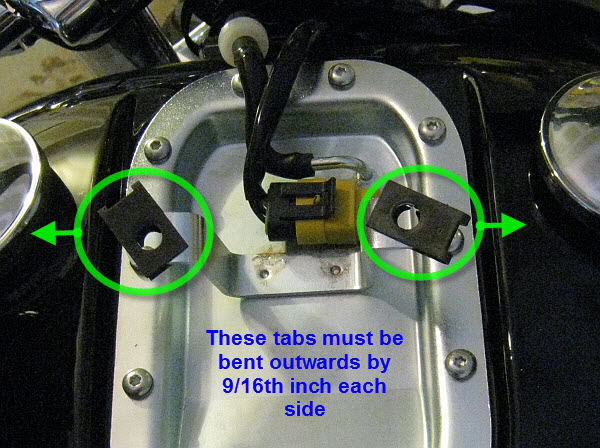
Using a suitable tool, *gently* bend each 'ear' outwards slightly, by about 9/16 inch. Make sure each ear is bent the same amount, so that when the console is bolted on, it remains centered on the tank. As you push the ears outward, the ends will tend to dip towards the ground. Grasp them with a pliers and bend them slightly in a upwards direction to make them once again level.
NOTE: The console mount on the top tank plate is only attached with a couple spot welds, so if you use a heavy hand to try and bend the tabs too much, it is possible to seperate the mount from the top plate -- and that could ruin your whole day, so use care.
MODIFICATION OF THE FXDF CONSOLE
Now that the mounting bracket on the tank is the right width, you will notice that the FXDB ears still rise too high above the tank to allow the FXDF console to mount solidly against the tank surface. You could somehow mangle and re-bend the tank ears to be in a lower position, but I thought the easier/safer solution would be to slightly mod the FXDF console itself. Here's how:
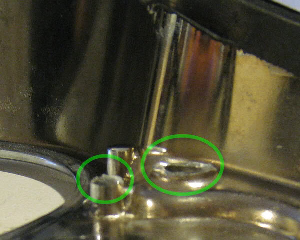
11) Turn the FXDF console over. There are two holes up near the Speedo that the two large mounting bolts go through. You will also note that on the underside of these holes, there are 2 cast-in spacers, one on each side of the console, plus a third smaller riser near the left side larger spacer. (See pict).
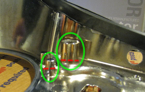
These spacers need to be cut off nearly flush to allow the console to sit at the proper heigth on the tank. Using a Dremel tool with a cut-off wheel attached, cut as much of the spacers off as possible to be even with the bottom of the console. (See pict) With my small cut-off wheel, I could only get about 9/10ths through the spacer, but at that point, the spacers can be easily snapped off the rest of the way when grasped and rocked gently with a large pliers in a back-and-forth motion. Near the spacer on the left side, there is also a smaller riser directly beside the spacer. I trimmed that one off by about 1/4 inch, just in case it might interfere.
12) Test fit the FXDF console to the FXDB tank. You may have to slightly adjust the bend of the tank top plate mounting ears to fit the holes in the FXDF console, but it should be pretty close.
FINAL ASSEMBLY
13) Install the keyswitch, Indicator module, and Speedo into the FXDF console.
14) Place the console on the tank, and reattach connectors for Speedo, Indicator light module, and keyswitch. Insert reset switch into hole on side of console and reinstall the screw-on rubber cover.
15) Reinstall three console mounting screws -- two by speedo, and one at the aft end of the tank.
16) Reconnect the battery.
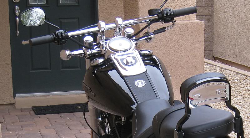
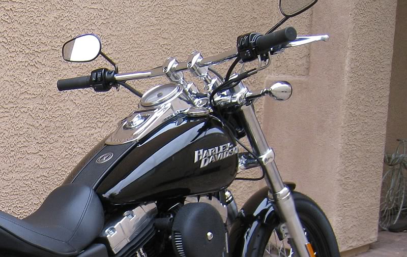
Upgrade complete!

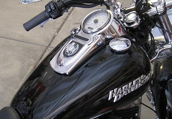
(I still have to add the leather console extension in this pic)
I had been debating how to move the FXDB keyswitch from the terribly inconvenient fork neck factory location to the top of the tank where God intended it to be.
I had seen some pretty slick installs from other forum members by either swapping in the FXDWG dash, or simply boring a hole in the FXDB dash, and installing the switch there. But I liked the bigger 5" speedo of the FXDC/F models, and decided to try upgrading the standard 4" console to an FXDF console which can accept the larger 5" speedo.
These instructions are for upgrading a 2010 FXDB. 2009 models should be the same, but 2008 and earlier may (or may not) be different.
WHAT YOU'll NEED
MAJOR COMPONENTS NEEDED (EST. PRICE):
67096-09 : SPEEDOMETER, MPH ($180)
71313-96A: IGNITION SWITCH ($75)
71211-04 : FXDF CONSOLE wTRIM ($95)
TRIM/SMALL PARTS NEEDED (EST. PRICE):
61250-06 : EXTENSION, CONSOLE, LEATHER ($35)
67190-89 : SEAL, SPEEDOMETER ($10)
67271-04A: CLAMP, SPEEDO ($5)
68113-99B: INDICATOR LIGHT ASBLY ($30)
69538-04A: BEZEL, INDICATOR LIGHT ($10)
71304-04 : IGN SWITCH LABEL ($14)
LOCAL : 8-32 x3/8" IGN SW SCREWS, 4 ($1)
LOCAL : 12AWG WIRE, STRANDED, 3FT ($3)
TOTAL FOR ALL BRAND NEW PARTS: $458.
(Est. prices are for brand-new parts from a forum HD vendor)
Buying all these items brand new can be expensive. However, I was able to get some good deals on a used console and speedo (the most expensive parts of this upgrade) here on the forum, so if you do some shopping for used parts, you can probably do the entire upgrade for $250 or less. Not bad considering the ignition switch alone is $75, and is probably the only part I would recommend buying new instead of used.
Notes:
* The 2009-2010 5" dyna speedo uses the same electrical connector and wiring scheme as the 2009-2010 4" speedo, and is a plug-and-play swap.
* When you buy the keyswitch, supply your original 4 digit key number, and they can match the new lock to your existing keys. After this upgrade, the original keyswitch will fucntion only as a fork lock.
* IMPORTANT: Note the mileage on the original speedo *before* you start. You will need this information later, and you can't get it once power is removed from the speedo. You are required by law to have the new speedo set to show the true mileage, or to add a label to the bike stating that the indicated mileage is not accurate, along with other info.
Instructions - Keyswitch relocation prep
1) Disconnect the battery (we're going to be cutting into power wires, and we don't want to short out anything)
2) Remove gas tank mounting bolts and move tank back about 3 inches to give a little working room. You do not have to disconnect any gas lines. Pull the plastic wire concealment panel out from under the frame under the gas tank to gain access to the ignition switch and wires.
3) Just under the frame neck, remove the small black plastic plug just UNDER the fork lock pin. Grab it with a pliers and just pull it straight out.
4) Peel back the glued-on printed metal ring surrounding the keyswitch.
5) You'll see a metal collar with holes in it surrounding the keyswitch. There is a special tool for removing this locking collar, but you don't need it. Get a sturdy pair of needlenose pliers, open them up wide and insert the tips into opposite holes in the locking collar. Twist the pliers CLOCKWISE (yes, clockwise!) to rotate the locking collar. It will rotate inwards into the frame, and when sufficiently rotated, it will allow the switch to slide towards the back of the bike, and out of the frame. Note: You dont actually have to remove the switch entirely - just move it out enough to be able to remove the 3-wire connector. After removal of the 3-wire connector, push the keyswitch back up into its original position and retighten the locking collar by rotating counter-clockwise. Reinstall the black plug under the fork lock pin.
EXTENDING THE IGNITION WIRES
6) In order for the ignition wires to reach the new keyswitch position on the tank, you'll need to cut and extend each of the 3 wires from the connector you just removed from the ignition approximately 8-12 inches. Two of the wires are 12AWG, and the third one is slightly lighter guage, but I had 12AWG wire available, so I used that on all three. These are very important wires that carry a good amount of current, so whatever method you choose to extend them, make sure the connections are VERY SOLID and well-insulated after you splice. I cut the original wires about 3 inches behind the connector, and soldered in a 12 inch extension for each one, followed up with shrink tubing and tape. Set it aside for now.
REMOVAL OF STOCK FXDB CONSOLE
7) Remove the three screws that hold the gas tank console in place. The two on top of the tank are easy, but for the third one at the aft end of the tank, you have to remove the seat to gain access.
8) Lift the FXDB console up, flip it over, and disconnect the speedo connector, the indicator lights module connector, and unscrew the rubber cover from the trip reset button. Remove the console from the bike.
SPLICING THE NEW INDICATOR LIGHTS
9) The new indicator light LED module from the FXDF uses a different connector that the one used by the FXDB. You will need to cut off the connectors, and splice each of the 7 wires from the FXDF indicator assembly onto the FXDB connector. It is rather tedious to do all 7, but the good thing is that the wire colors are coded the same, so all you have to do is match the colors up, do your solder/splice for each one, and you're good to go. (See wiring pics below)
MODIFICATION OF FXDB TANK BRACKET
The bracket attached to the tank top plate of the FXDB can be used to attach the FXDF console, but it needs to be slightly modified.
10) There are two 'ears' or brackets that stick up from the top plate of the gas tank. These need to be bent slightly to accomodate the wider width of the attachment points used by the FXDF console.
The attachement hole centers on the FXDF console are 4-1/4" appart, and those on the FXDB are approximately 3-1/8" apart, so we need to spread the mounting tabs apart about 9/16 inch per side.
Using a suitable tool, *gently* bend each 'ear' outwards slightly, by about 9/16 inch. Make sure each ear is bent the same amount, so that when the console is bolted on, it remains centered on the tank. As you push the ears outward, the ends will tend to dip towards the ground. Grasp them with a pliers and bend them slightly in a upwards direction to make them once again level.
NOTE: The console mount on the top tank plate is only attached with a couple spot welds, so if you use a heavy hand to try and bend the tabs too much, it is possible to seperate the mount from the top plate -- and that could ruin your whole day, so use care.
MODIFICATION OF THE FXDF CONSOLE
Now that the mounting bracket on the tank is the right width, you will notice that the FXDB ears still rise too high above the tank to allow the FXDF console to mount solidly against the tank surface. You could somehow mangle and re-bend the tank ears to be in a lower position, but I thought the easier/safer solution would be to slightly mod the FXDF console itself. Here's how:
11) Turn the FXDF console over. There are two holes up near the Speedo that the two large mounting bolts go through. You will also note that on the underside of these holes, there are 2 cast-in spacers, one on each side of the console, plus a third smaller riser near the left side larger spacer. (See pict).
These spacers need to be cut off nearly flush to allow the console to sit at the proper heigth on the tank. Using a Dremel tool with a cut-off wheel attached, cut as much of the spacers off as possible to be even with the bottom of the console. (See pict) With my small cut-off wheel, I could only get about 9/10ths through the spacer, but at that point, the spacers can be easily snapped off the rest of the way when grasped and rocked gently with a large pliers in a back-and-forth motion. Near the spacer on the left side, there is also a smaller riser directly beside the spacer. I trimmed that one off by about 1/4 inch, just in case it might interfere.
12) Test fit the FXDF console to the FXDB tank. You may have to slightly adjust the bend of the tank top plate mounting ears to fit the holes in the FXDF console, but it should be pretty close.
FINAL ASSEMBLY
13) Install the keyswitch, Indicator module, and Speedo into the FXDF console.
14) Place the console on the tank, and reattach connectors for Speedo, Indicator light module, and keyswitch. Insert reset switch into hole on side of console and reinstall the screw-on rubber cover.
15) Reinstall three console mounting screws -- two by speedo, and one at the aft end of the tank.
16) Reconnect the battery.
Upgrade complete!
(I still have to add the leather console extension in this pic)
Last edited by KentFXD; 02-06-2011 at 11:50 AM.
#2
09-29-2010, 08:39 PM
Outstanding HDF Member
#4
09-30-2010, 01:03 AM
Cruiser
Join Date: Oct 2009
Location: Colorado
Posts: 151
Likes: 0
Received 0 Likes
on
0 Posts
#6
09-30-2010, 01:14 AM

#7
10-30-2010, 10:24 AM
Cruiser
Join Date: Jan 2010
Location: Topeka, Ks
Posts: 188
Likes: 0
Received 0 Likes
on
0 Posts
Trending Topics
#8
10-30-2010, 12:52 PM
Cruiser
Join Date: Dec 2008
Location: Kansas
Posts: 127
Likes: 0
Received 0 Likes
on
0 Posts
#9
12-04-2010, 10:49 PM
Join Date: Sep 2006
Location: Las Vegas, NV
Posts: 113
Likes: 0
Received 0 Likes
on
0 Posts