Auxiliary power plug with a lot of pictures
#21
 08-31-2014, 04:11 PM


4th Gear
Join Date: Aug 2014
Location: Kalifornia
Posts: 8
Likes: 0
Received 0 Likes
on
0 Posts
QUOTE=Big H;8348782]Recently there has been some question of where the auxiliary power plug is on our softails. Yes, the discussion of the elusive orange wire with the white tag stripe is what I am referring to. I decided to show some pictures of the plug, where it's located, and what I did to utilize it.
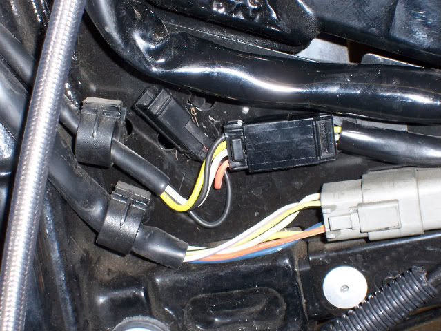
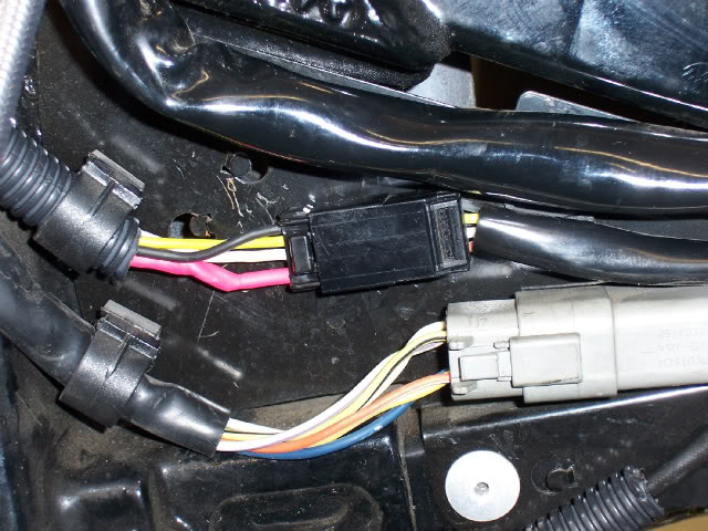
With the fuel tank off of my 2004 EFI Fat Boy, on the left side of the neck, this is what the wiring harness looks like.
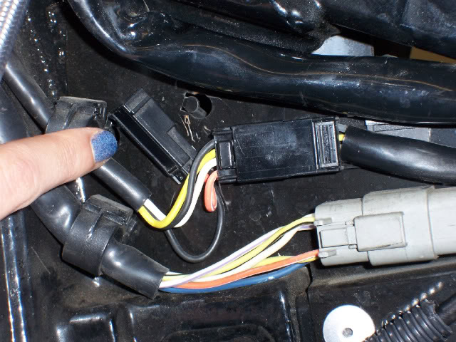
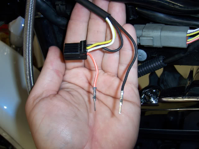
My daughter's finger is pointing to the unused plug here. It is part of the harness that goes to the headlight itself.
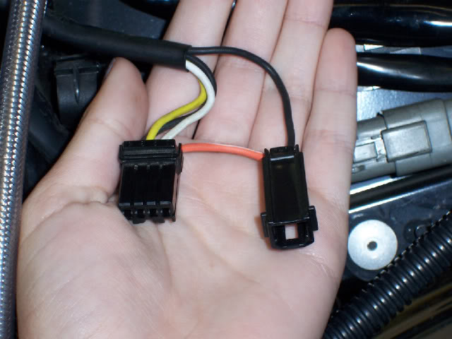
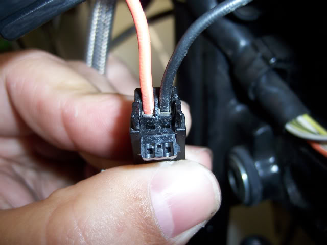
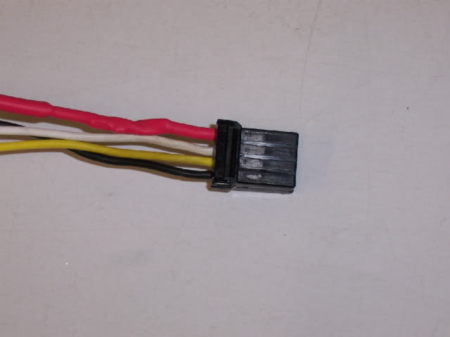
With the headlight harness unplugged, it's quite easy to distinguish the black, yellow, and white wires that run to the bike's 3-prong, H4 headlight plug. The auxiliary plug is seen on the right with its tell-tale orange wire with white tag stripe. The black wire is a ground that shares the same ground circuit as the headlight itself.
I could not find the correct plug in the service parts or schematics to mate to this plug. My local dealer searched and came up with zero. Even the HD power port for the softails does not have the correct mate for this. My solution was to swap the plug. I started by opening the wire retainer end of the part.
That allowed me to remove the pins from the plug itself, as you can see here.
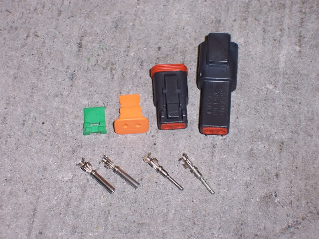
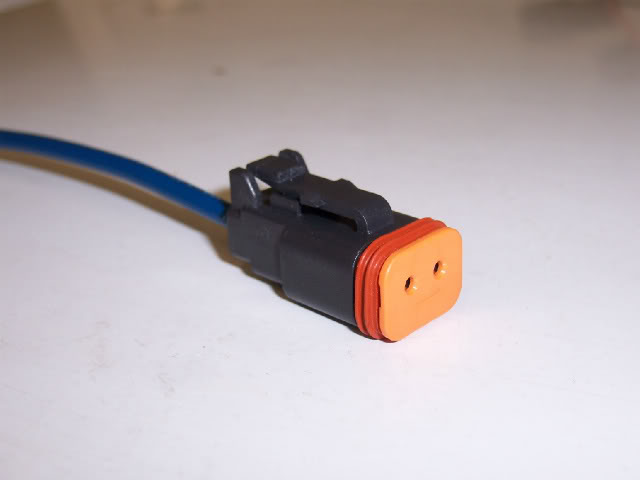
I replaced the errant plug with a 2-pin Deutsch connector that I sourced from my HD dealer. All the parts shown are individual part numbers and came to $19.14 with sales tax. Your price may vary and choice of place to purchase said parts could vary as well.
The plug seal needed to be removed first.
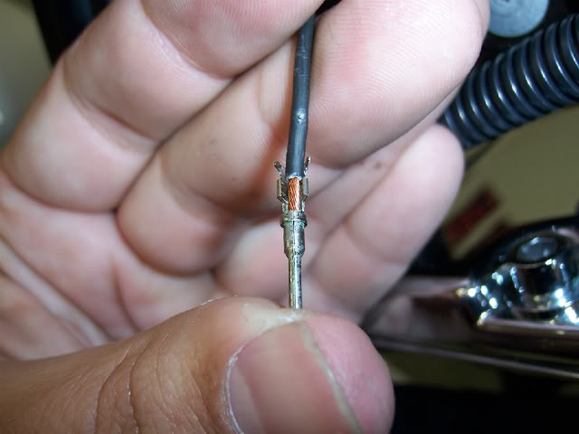
The seal was slid over the wires and then the original pins were cut off and the wires stripped to the proper length.
My decision was to replace the female plug already on the bike with the new female Deutsch connector. It gets the male pins. As you can see, the proper wire length has the wire all the way in the socket, the first set of tangs has to catch the bare wire, and the second set of tangs grabs the wire covering. I did not have the correct crimping tool so I folded the tangs over best I could and soldered them once complete.
Both male pins were on the factory wires ready to be soldered permanently.
It's a simple matter of plugging the pins into the rear of the socket housing, sliding the seal into position, and putting the pin lock inside the socket (green one from picture 6). At this point my bike would now be ready to accept the factory accessories listed in the catalog (power port, GPS, etc...).
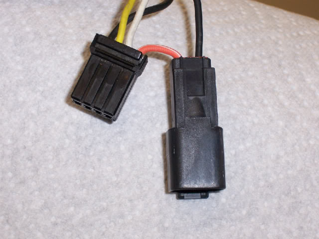
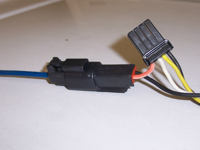
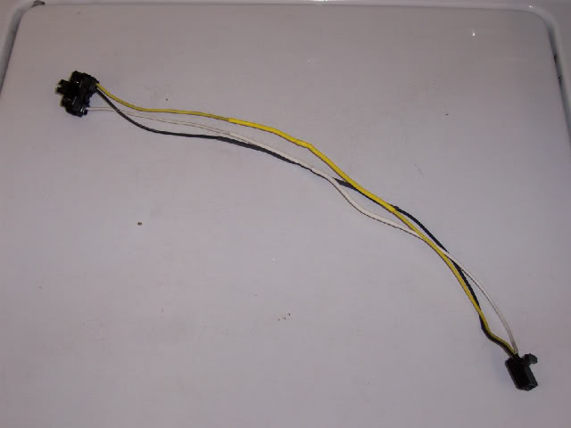
You can see what the entire headlight harness with the updated plug looks like removed from the bike.
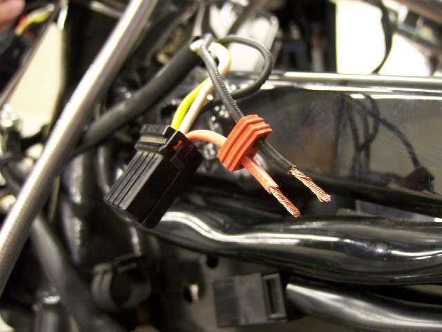
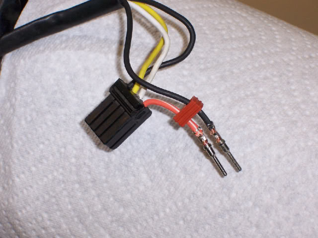
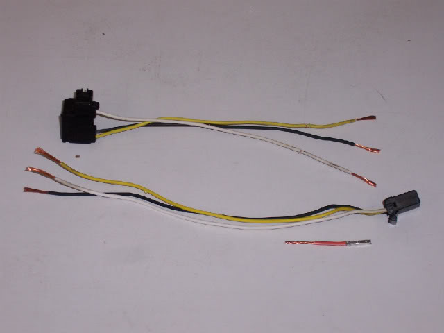
That was not my plan though. I wanted to utilize the accessory power supply to run my passing lamps from an on/off switch, allowing my lights to work with both the low and high beam. Only the power circuit was necessary so I wired the male end of the Deutsch connector with the female plugs as seen here (completed plug). I made sure to put the wire on the side that will mate to the orange/white wire.
All together here, you can see how I omitted the ground wire since it would not used. The passing lamps are chassis grounded inside the housings.
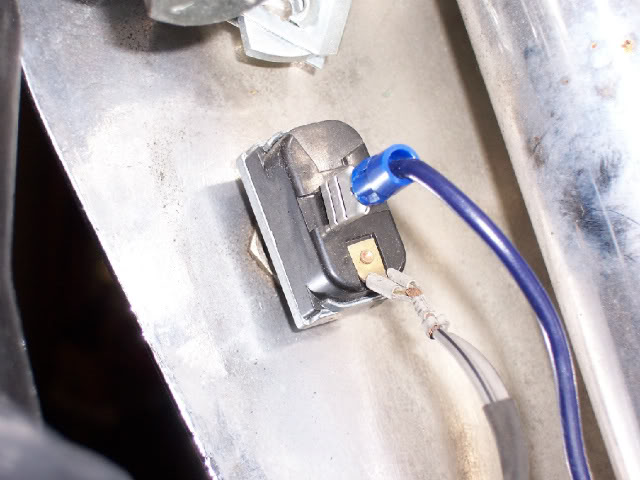
Inside the headlight nacelle (freight train-style), it was a simple matter of placing the spade connector on the switch. From this point the passing lamps would be on their own power circuit and would not be influenced by the low/high beam switch. Manual control (with ignition on) is handled by the on/off switch accessible from the rear of the nacelle.
Something did not set right with me and it was the fact that I only wanted to use the power circuit offered by the orange/white wire. So in effect, I ran an extra plug for absolutely nothing. Begrudgingly I pulled the harness back off the Fat Boy, de-pinned the Deutsch connector, pulled the orange wire pin from the headlight plug, and cut the headlight harness apart so I could rid myself of the butt connectors (the butt connectors from the nacelle conversion never sat right with me).
Just so happens that I have plenty of heat shrink tubing around so I soldered the headlight wires together and covered them with matching heat shrink.
After soldering a length of wire to the orange/white wire, I heat shrinked it with red tubing (no orange in my inventory), and put the pin back in the stock headlight harness plug.
Covered with split loom and plugged back into the motorcycle, it nearly looked original equipment. Best part for me was there was no extra plug.
Your results and needs may vary but I am completely happy about the final revision. My headlight is a low/high HID and the passing lamps are no longer T-tapped from the low beam circuit before my HID's ballast. All the connections are now solid electrical connections that will last for years to come and provide me with worry-free miles.[/QUOTE]
With the fuel tank off of my 2004 EFI Fat Boy, on the left side of the neck, this is what the wiring harness looks like.
My daughter's finger is pointing to the unused plug here. It is part of the harness that goes to the headlight itself.
With the headlight harness unplugged, it's quite easy to distinguish the black, yellow, and white wires that run to the bike's 3-prong, H4 headlight plug. The auxiliary plug is seen on the right with its tell-tale orange wire with white tag stripe. The black wire is a ground that shares the same ground circuit as the headlight itself.
I could not find the correct plug in the service parts or schematics to mate to this plug. My local dealer searched and came up with zero. Even the HD power port for the softails does not have the correct mate for this. My solution was to swap the plug. I started by opening the wire retainer end of the part.
That allowed me to remove the pins from the plug itself, as you can see here.
I replaced the errant plug with a 2-pin Deutsch connector that I sourced from my HD dealer. All the parts shown are individual part numbers and came to $19.14 with sales tax. Your price may vary and choice of place to purchase said parts could vary as well.
The plug seal needed to be removed first.
The seal was slid over the wires and then the original pins were cut off and the wires stripped to the proper length.
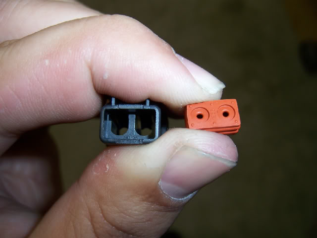
My decision was to replace the female plug already on the bike with the new female Deutsch connector. It gets the male pins. As you can see, the proper wire length has the wire all the way in the socket, the first set of tangs has to catch the bare wire, and the second set of tangs grabs the wire covering. I did not have the correct crimping tool so I folded the tangs over best I could and soldered them once complete.
Both male pins were on the factory wires ready to be soldered permanently.
It's a simple matter of plugging the pins into the rear of the socket housing, sliding the seal into position, and putting the pin lock inside the socket (green one from picture 6). At this point my bike would now be ready to accept the factory accessories listed in the catalog (power port, GPS, etc...).
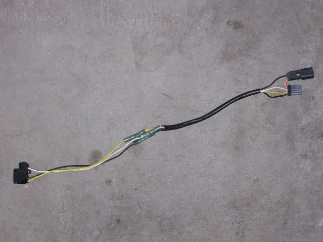
You can see what the entire headlight harness with the updated plug looks like removed from the bike.
That was not my plan though. I wanted to utilize the accessory power supply to run my passing lamps from an on/off switch, allowing my lights to work with both the low and high beam. Only the power circuit was necessary so I wired the male end of the Deutsch connector with the female plugs as seen here (completed plug). I made sure to put the wire on the side that will mate to the orange/white wire.
All together here, you can see how I omitted the ground wire since it would not used. The passing lamps are chassis grounded inside the housings.
Inside the headlight nacelle (freight train-style), it was a simple matter of placing the spade connector on the switch. From this point the passing lamps would be on their own power circuit and would not be influenced by the low/high beam switch. Manual control (with ignition on) is handled by the on/off switch accessible from the rear of the nacelle.
Something did not set right with me and it was the fact that I only wanted to use the power circuit offered by the orange/white wire. So in effect, I ran an extra plug for absolutely nothing. Begrudgingly I pulled the harness back off the Fat Boy, de-pinned the Deutsch connector, pulled the orange wire pin from the headlight plug, and cut the headlight harness apart so I could rid myself of the butt connectors (the butt connectors from the nacelle conversion never sat right with me).
Just so happens that I have plenty of heat shrink tubing around so I soldered the headlight wires together and covered them with matching heat shrink.
After soldering a length of wire to the orange/white wire, I heat shrinked it with red tubing (no orange in my inventory), and put the pin back in the stock headlight harness plug.
Covered with split loom and plugged back into the motorcycle, it nearly looked original equipment. Best part for me was there was no extra plug.
Your results and needs may vary but I am completely happy about the final revision. My headlight is a low/high HID and the passing lamps are no longer T-tapped from the low beam circuit before my HID's ballast. All the connections are now solid electrical connections that will last for years to come and provide me with worry-free miles.[/QUOTE]


#24
07-01-2016, 10:38 AM
Intermediate
Hi TryGuy!
Beautiful post!
Taking inspiration from what you reported, I tried to find this connector on my FXSTC 2010.... but with no results at all!
I've only discovered the grey diagnostic connector.....
Can you (or anyone else in this wonderful forum) help me?
I'd like to use it to power the accent leds kit and a voltmeter (you never know!)....
Lamps everybody!
Fiorenzo and The Doctor from Italy
#25
07-01-2016, 06:38 PM

Road Captain
Are you looking under the seat? Or, under the tank? I think it should be under th tank, on the left side of the frame.
Do you have the Factory Service Manual? In mine (for my '14 Slim), It talks about this fender tip connection when it talks about the headlight assembly.... It's in the Electrical section.
Do you have the Factory Service Manual? In mine (for my '14 Slim), It talks about this fender tip connection when it talks about the headlight assembly.... It's in the Electrical section.
#26
07-02-2016, 10:17 AM
Intermediate
Are you looking under the seat? Or, under the tank? I think it should be under th tank, on the left side of the frame.
Do you have the Factory Service Manual? In mine (for my '14 Slim), It talks about this fender tip connection when it talks about the headlight assembly.... It's in the Electrical section.
Do you have the Factory Service Manual? In mine (for my '14 Slim), It talks about this fender tip connection when it talks about the headlight assembly.... It's in the Electrical section.
Under the seat I can only see the datalink connector...
I can't see anything under the tank... only wirings, but apparently no connectors..
What I need is a switched power connector and I don't think that the B+ connector is switched... I think it is Hot, straight from the positive pole of the battery.
I'm thinking about using a piggyback fuse on the accessory fuse.
Or maybe it's better to take power from an orange/white wire (anywhere)?
Suggestions?
#27
07-02-2016, 01:06 PM

Under the tank on the left side should be a couple of connectors 1 Headlight 2 The connector described above and 3 Fuel gauge connector. The power for the light comes from the Auxiliary fuse in the fuse block under the seat. The connectors will be mounted right up tight against the frame backbone maybe under the rubber cover on the front of the tank. There is a pair of channels on both sides of the frame under the back side of the tank that are just plastic wrap around with a snapping top for routing the cabling going to the forward sections of the bike from the seat. Take another look and you may notice what was described.
#28
07-02-2016, 01:12 PM
Intermediate
Under the tank on the left side should be a couple of connectors 1 Headlight 2 The connector described above and 3 Fuel gauge connector. The power for the light comes from the Auxiliary fuse in the fuse block under the seat. The connectors will be mounted right up tight against the frame backbone maybe under the rubber cover on the front of the tank. There is a pair of channels on both sides of the frame under the back side of the tank that are just plastic wrap around with a snapping top for routing the cabling going to the forward sections of the bike from the seat. Take another look and you may notice what was described.
I'm afraid of accessing the connectors under the tank. Is it an easy operation?
#29
07-02-2016, 05:16 PM
Road Captain
I was messing with mine today. My bike is a '14.
When I was looking at the manual about auxiliary lighting, I came across the section about replacing the headlight assembly, which includes the wiring loom for the headlight (and this orange and white wire that is labelled for the fender tip running lamp for Heritage models). It stated that I could unbolt the tank and slide it back without removing the gas lines, etc.
It actually did work just like they said! I removed the bolt under the front of the tank, the bolt at the back and the screw holding the tanks bib. I wiggled the tank bank, and sure enough, right there on the left side was the headlight assembly connector with the little piggyback connector with an orange and black wire, just like in the OP's pictures.
The one problem is that on the newer bikes, all of the lighting is controlled through the Body Control Module or BCM. It measure the load on every wire and if the load is not exact, it throws a code.
On your 2010, this shouldn't be a problem.
On my bike, I've had to run a wire straight for the positive terminal of the battery, to get my LED passing lamps to function without throwing a code and messing with the fuel level indicators.
#30
07-06-2016, 01:10 PM
Intermediate
Tried to find out the connector with no result.
So I've finally installed a piggyback fuse on the accessori fuse and I've used it to power spotlights and accent lights!
Everything works fine!
p.s. I've also installed a wonderful engine guard!

p.p.s. now I'll start looking for something else... a new handlebar, maybe???
Lamps,
So I've finally installed a piggyback fuse on the accessori fuse and I've used it to power spotlights and accent lights!
Everything works fine!
p.s. I've also installed a wonderful engine guard!
p.p.s. now I'll start looking for something else... a new handlebar, maybe???
Lamps,
The following users liked this post:
Musashi (09-18-2022)

Thread
Thread Starter
Forum
Replies
Last Post

