
Brake light question
#11
 06-26-2016, 04:24 PM

Ok im sitting here looking at it now.. Does this method require wire splicing or even soldering? Buying new connection ports or is it plug and play? Heres what im looking at...
Original 6 point tail light bracket (would leave it like this but turn wires are too short and seat will crush it.) And the wire connector unit that was under the fender that ran to the back
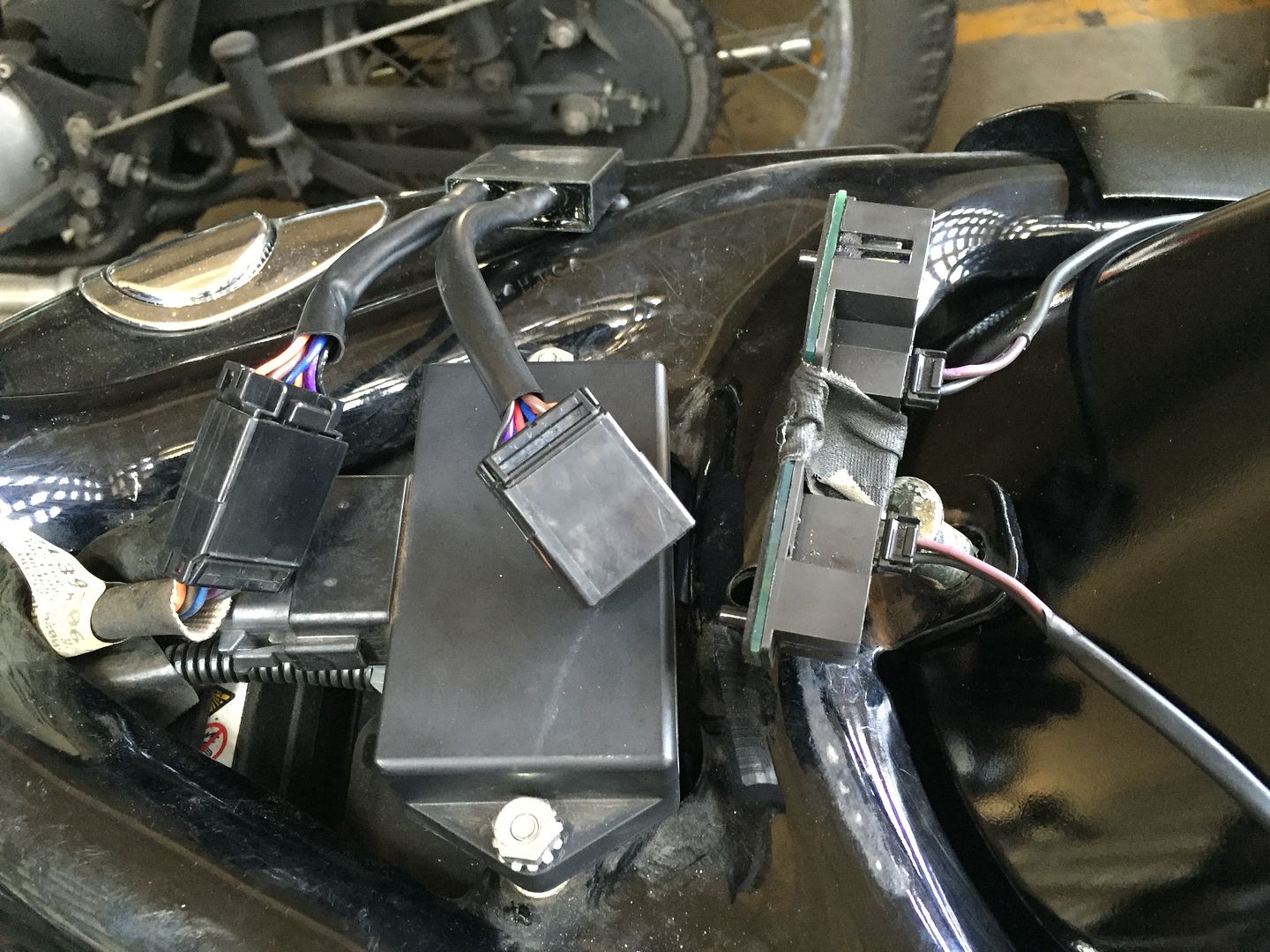
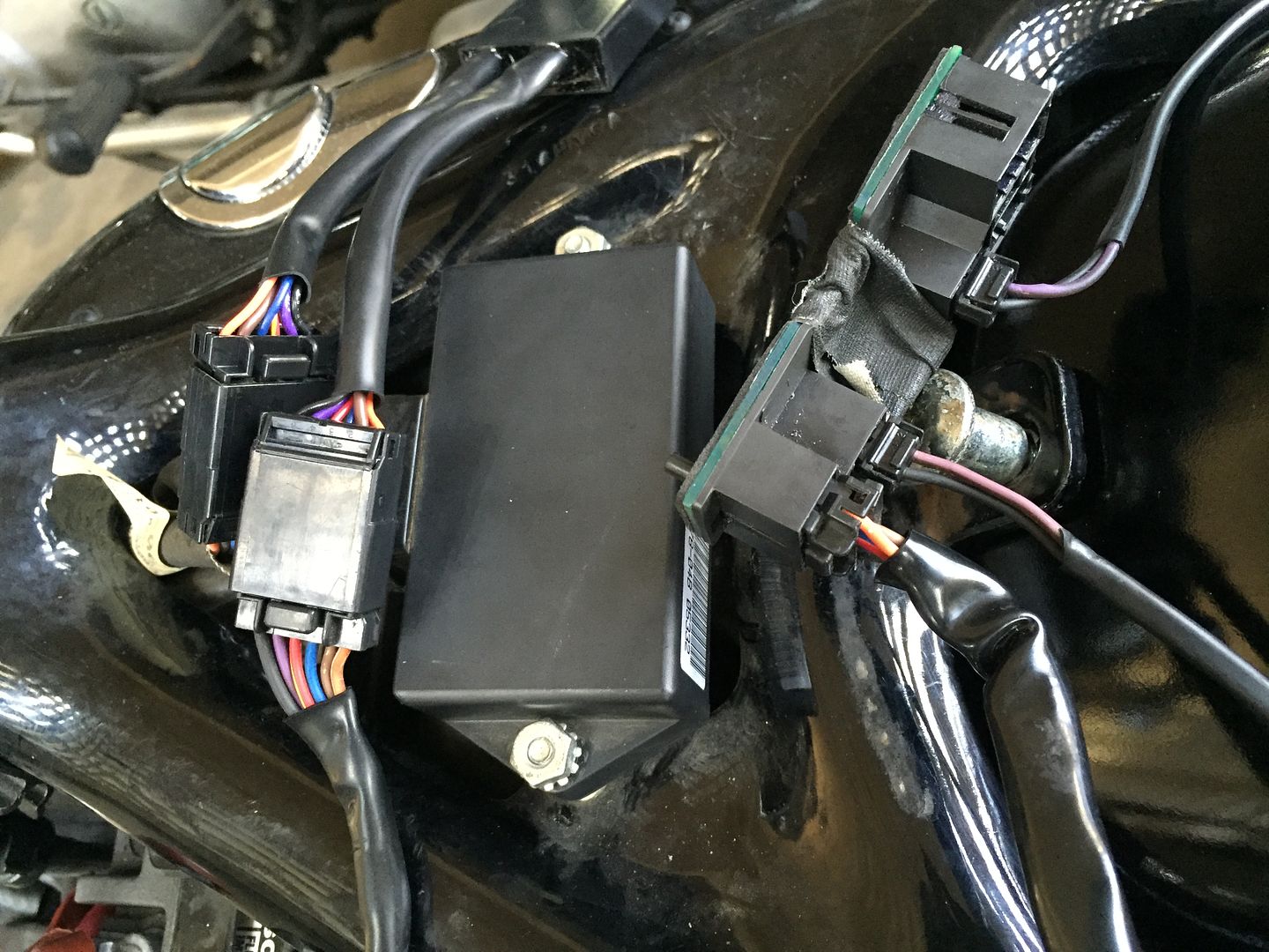
I looked at the diagram and what you wrote.. But im mainly confused when you say just throw the brake light unit out. Where will the turn wires connect too? The plugs dont match up for the turns to connect into the turn module without the 6point unit from the tail light
#13
06-27-2016, 06:40 AM
Yes you have to cut the wires from the tail light and splice them. The module you bought I assume you know goes under your seat. Take the long wires that run under the fender that you cut away from the tail light and splice the turn signal wires to the wires coming from the turn signals. Don't worry about the wires that are coming out of your tail light. They are not needed. The module you bought is used normally just for making your turn signals run brake and turn and to work in tandom with your original tail light. That is why none of the other wires are needed because the tail light is eliminated now so you only need to find the two turn signal wires in the group of wires running under your fender. Sorry I didn't take any pictures when doing mine
#14
06-27-2016, 06:46 AM
Just to add a step by step. Pull the wires out of the rubber under the fender. You need total of three wires in that group. Black is ground. If I remember correctly purple is left turn and brown is right turn. Connect left and right turn signals black wires to the black wire on the bike by either solder or wire connectors. Then the purple to the left turn signal and the brown to the right. Don't worry if the brown wire isn't the same color as the actual turn signal wire. It ran to that circuit board originally then came back to the turn signal as purple.
#15
06-27-2016, 07:56 AM
#16
06-27-2016, 09:00 AM
Dk sells lights that go in place of your license plate bolts. For that you would use one of the striped wires in that cluster. They are the running lights. That is what I used except the lights I bought also had red lights in the tips and I wired them to the brake for extra brake lighting. Wasn't worth it though because they aren't bright enough to be noticed when braking. I had a buddy ride the bike and I followed him and the regular brake lights drowned them out to the point the my weren't noticeable.
#18
06-28-2016, 04:55 PM
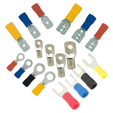
ok last major question before i get the wire cutting. i want to add connectors... but will these wire crimp style male/female connectors work? they are quick attach/detach. suppose i crimped and connected each wire individually instead of the plug clips like the ones from the harness. im afraid of throwing electrical codes so im being hesitant
and this is my color added diagram just to make it easier on my eyes
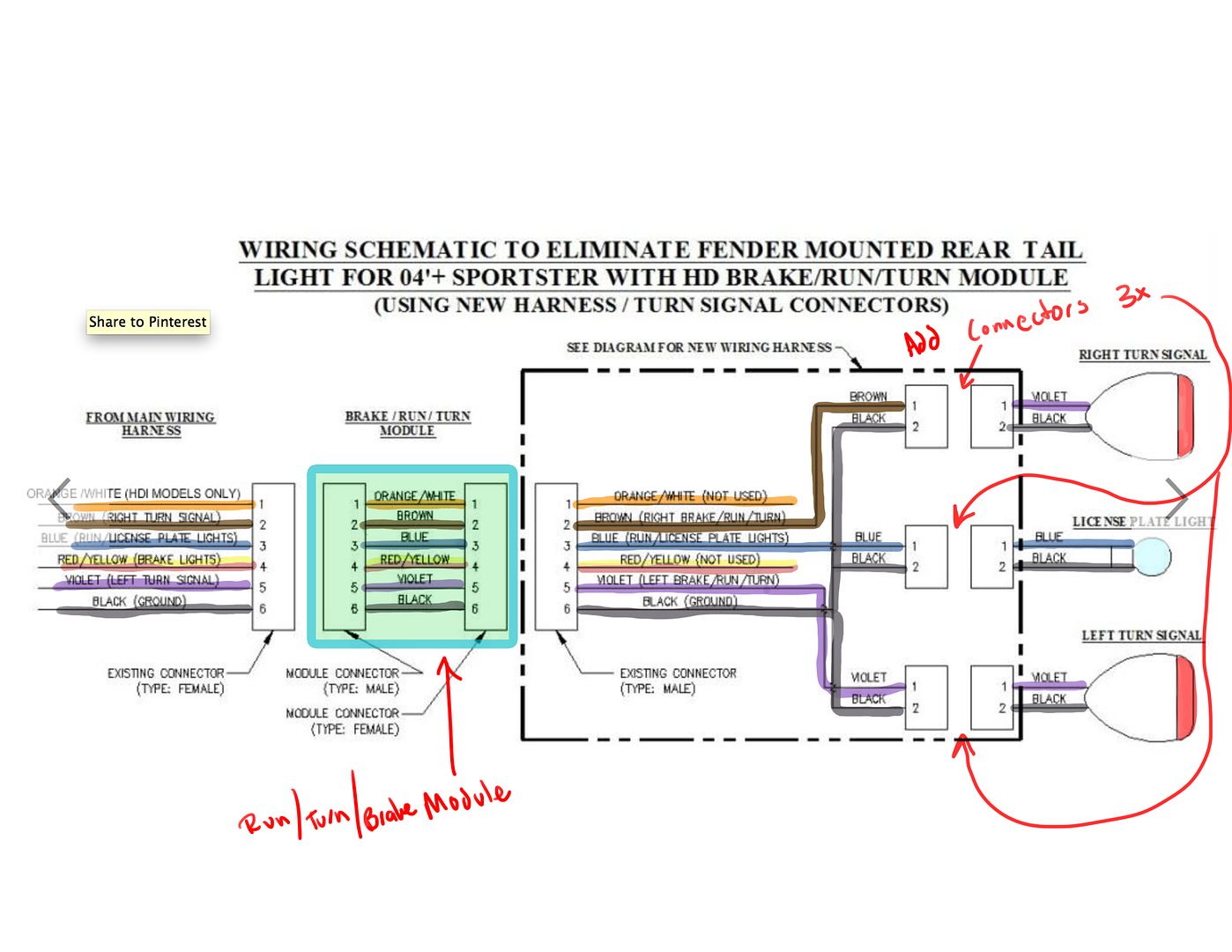

and this is my color added diagram just to make it easier on my eyes

#19
06-28-2016, 05:02 PM
Seasoned HDF Member
#20
06-28-2016, 05:09 PM