
HD Audio iPod Interface Install - 2011 RGC
#1
 03-17-2011, 08:43 AM

iPod Interface-to avoid cutting the tip of my glove - Part Number: 76476-10
Needed list of parts (no, just buying the kit is not enough )
)
76476-10 Kit-iPod Interface Touring
90200002 Tether, rh-s'bag (if installing in saddlebag)
69200033 Kit-connector/seal-pin,iPod/NI
72648-11 Harness, iPod intermediate (if installing in saddlebag)
12100001 Grommet for the hole you have to drill on the saddlebag (if installing in saddlebag )
First off, remove the front fairing. Don't know how?? Here you go: Front Fairing Removal-Install 2011 RGC
NOTE: Instructions are for a 2011 Road Glide Custom. Here is a note from Carl on doing this on an 2010-11 Ultra:
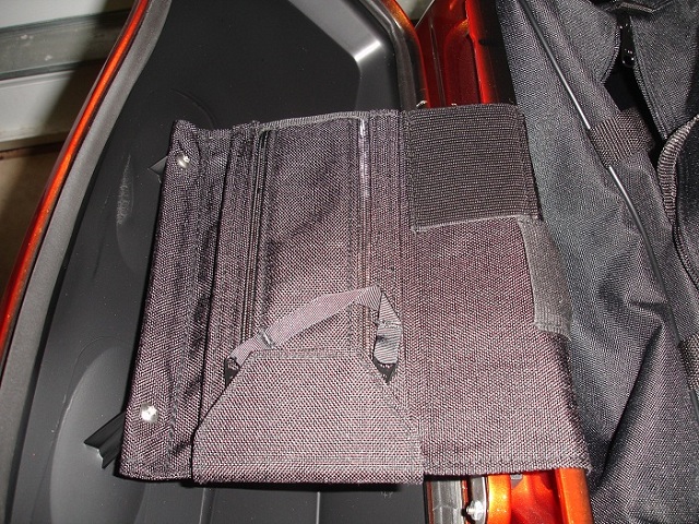
Install the pouch in the saddlebag. This is easy, just unbolt the old cloth stop, install the pouch in its place, do not forget the metal inserts.
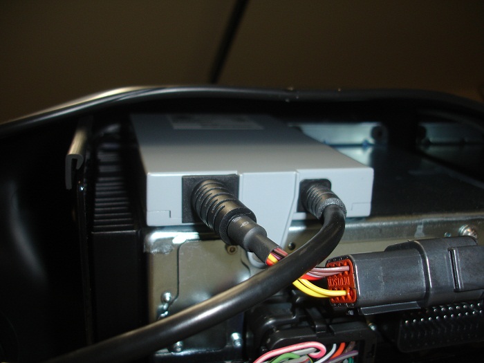
The box on top of the radio, also easy, it has two nipples that align in the front with a base, fixed with a bolt in the back and you are done.
I was able to do so because I found a post here in hdforums with some very good guidelines:
That information with the install instructions helped me make this an easy install.
Interface installed on top of the radio:
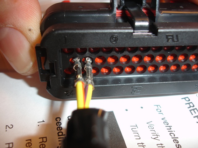
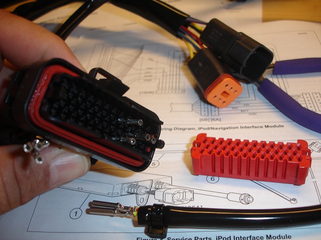
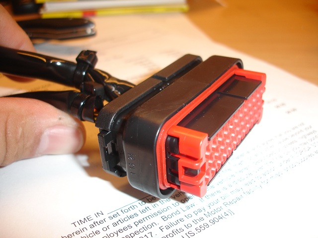
Inserting the pins in the 69200033 conector:
Edit: The plug comes with the orange wedgelock mounted in the open position. I only removed it for showing you what it looks like on the inside. Do not remove it. Tyco says the connector is shipped with the wedgelock in the "open" position to allow wires to be inserted; and, says "never remove the red wedgelock from the connector."
Just make sure the female conectors go in until the click. Once all connectors are in, push the wedgelock in all the way.

Needed list of parts (no, just buying the kit is not enough
)76476-10 Kit-iPod Interface Touring
90200002 Tether, rh-s'bag (if installing in saddlebag)
69200033 Kit-connector/seal-pin,iPod/NI
72648-11 Harness, iPod intermediate (if installing in saddlebag)
12100001 Grommet for the hole you have to drill on the saddlebag (if installing in saddlebag )
First off, remove the front fairing. Don't know how?? Here you go: Front Fairing Removal-Install 2011 RGC
NOTE: Instructions are for a 2011 Road Glide Custom. Here is a note from Carl on doing this on an 2010-11 Ultra:
Just a note on the parts list above regarding the 69200033 harness. If you have an Ultra or have added the non-Ultra overlay harness (used when adding HD's XM, CB, rear speakers/pods to the King Tour Pak), you won't need that harness since your bike already has 35 wire connector plugged into the HK. Ditto those who have added the HD intercom kit, p/n 77107-08 since that kit also includes 35 wire connector.
Carl
Carl
Install the pouch in the saddlebag. This is easy, just unbolt the old cloth stop, install the pouch in its place, do not forget the metal inserts.
The box on top of the radio, also easy, it has two nipples that align in the front with a base, fixed with a bolt in the back and you are done.
I was able to do so because I found a post here in hdforums with some very good guidelines:
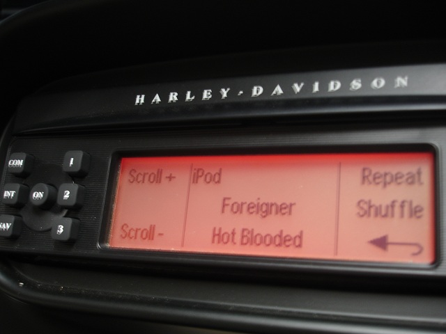
I just installed my iPod Interface on my 2011 RGU today, wired per the 09/14/2010 revision instructions.....it works flawlessly, and the music quality is much better than when I had the iPod playing through the front AUX port with a mini-jack.
Couple of install notes:
1) On the supplied iPod Y harness, at the end where the bare pin wires emerge from the black protective cover, cut the factory tyrap off and cut back the black protective covering approx. 2", to expose more of the colored wires. This will allow the wires to be integrated into the 35 pin AMP connector much easier, and without undue strain on this supplied iPod Y harness wires.
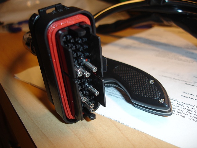
2) To correctly install the iPod Y harness pins into the 35 pin AMP connector, carefully remove the RED plastic 35-hole alignment block on the face of the AMP connector. This is easily done by carefully prying OUT each of the two very small black clips holding the RED alignment block on each side, while pulling the RED block straight out. This will allow the inserted pins from the iPod harness to click into the primary lock inside the 35 pin AMP connector. When done, carefully click the RED block back onto the AMP connector.
3) Try to route the Y harness wires into the 35 pin connector with some thought as to keeping the wires uniform to reduce strain.
4)It may be confusing as to what they want you to do with the two (1 male / 1 female) 6 pin connectors on the Y harness. You need to search your existing motorcycle harness near the rear of the HK stereo, and find an already mated pair of identical connectors. Disconnect them, and "T" these iPod Y harness 6-pin connectors into the existing motorcycle harness.
5) The single larger connector is self explanitory, it connects to the iPod interface box you mounted on the top of the HK radio.
6) The strange (6 pin) smaller connector that remains after connecting everything is for the NAVIGATION unit that you can buy from HD. This will get capped and stowed if you don't have a Zumo GPS unit. If you do, this connects to the handlebar/dash interface for the Zumo.
7) The actual iPod interface cable that connects to the iPod is self explanitory. It plugs the round end into the iPod interface that you installed on top of the HK unit.
Couple of install notes:
1) On the supplied iPod Y harness, at the end where the bare pin wires emerge from the black protective cover, cut the factory tyrap off and cut back the black protective covering approx. 2", to expose more of the colored wires. This will allow the wires to be integrated into the 35 pin AMP connector much easier, and without undue strain on this supplied iPod Y harness wires.
2) To correctly install the iPod Y harness pins into the 35 pin AMP connector, carefully remove the RED plastic 35-hole alignment block on the face of the AMP connector. This is easily done by carefully prying OUT each of the two very small black clips holding the RED alignment block on each side, while pulling the RED block straight out. This will allow the inserted pins from the iPod harness to click into the primary lock inside the 35 pin AMP connector. When done, carefully click the RED block back onto the AMP connector.
3) Try to route the Y harness wires into the 35 pin connector with some thought as to keeping the wires uniform to reduce strain.
4)It may be confusing as to what they want you to do with the two (1 male / 1 female) 6 pin connectors on the Y harness. You need to search your existing motorcycle harness near the rear of the HK stereo, and find an already mated pair of identical connectors. Disconnect them, and "T" these iPod Y harness 6-pin connectors into the existing motorcycle harness.
5) The single larger connector is self explanitory, it connects to the iPod interface box you mounted on the top of the HK radio.
6) The strange (6 pin) smaller connector that remains after connecting everything is for the NAVIGATION unit that you can buy from HD. This will get capped and stowed if you don't have a Zumo GPS unit. If you do, this connects to the handlebar/dash interface for the Zumo.
7) The actual iPod interface cable that connects to the iPod is self explanitory. It plugs the round end into the iPod interface that you installed on top of the HK unit.
Xzotik, you will have a 6B (male) connector left over/unused from the NIM harness. What I was explaining in my earlier posts was that the instructions referring to the separation of connector 6 don't apply to FLHX, etc. since those bike's don't have an audio harness installed with a 6A connector connected to the 6B connector (thus creating the "connector 6").
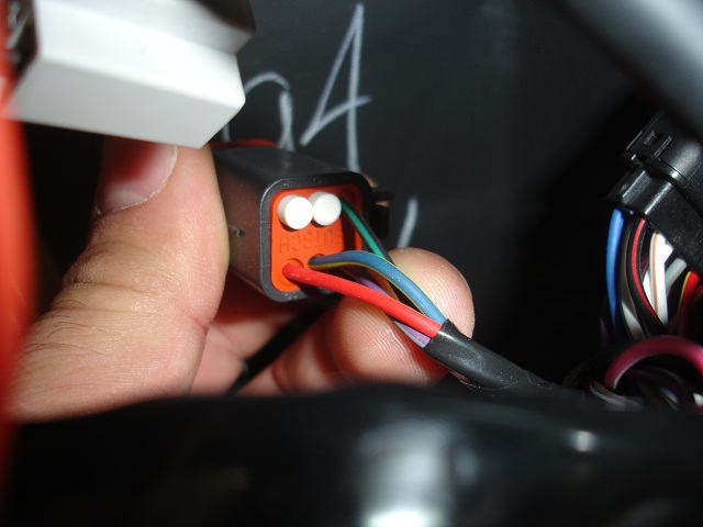
So, on FLHX you simply use the 6A connector (female six wire connector) on the NIM harness to connect to the bike's 6B connector (male six wire connector), leaving an unused 6B (male) connector on the NIM harness.
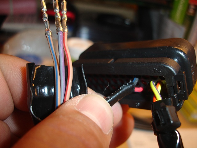
You'll know you have the bike's 6B connector by the wire colors. There will four wires in the six-wire connector: black/green, red/orange, blue/yellow, and violet/gray.
Good luck with your project.
Carl
So, on FLHX you simply use the 6A connector (female six wire connector) on the NIM harness to connect to the bike's 6B connector (male six wire connector), leaving an unused 6B (male) connector on the NIM harness.
You'll know you have the bike's 6B connector by the wire colors. There will four wires in the six-wire connector: black/green, red/orange, blue/yellow, and violet/gray.
Good luck with your project.
Carl
Interface installed on top of the radio:
Inserting the pins in the 69200033 conector:
Edit: The plug comes with the orange wedgelock mounted in the open position. I only removed it for showing you what it looks like on the inside. Do not remove it. Tyco says the connector is shipped with the wedgelock in the "open" position to allow wires to be inserted; and, says "never remove the red wedgelock from the connector."
Just make sure the female conectors go in until the click. Once all connectors are in, push the wedgelock in all the way.
Last edited by wachuko; 04-27-2011 at 03:05 PM. Reason: Added link to removing the front fairing
The following users liked this post:
Cobal (02-25-2017)
#2
03-17-2011, 08:43 AM
More...
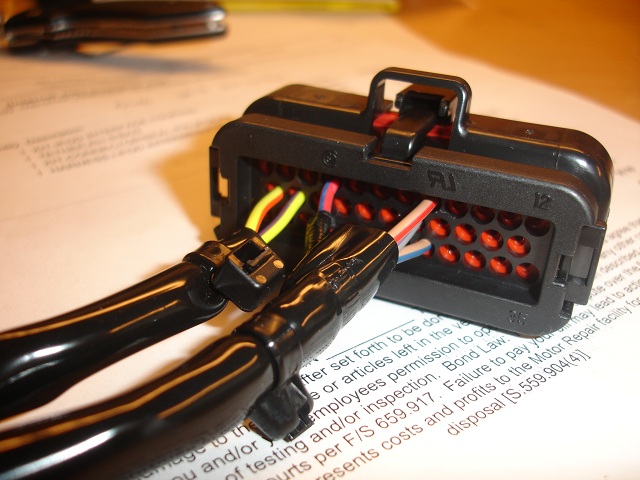
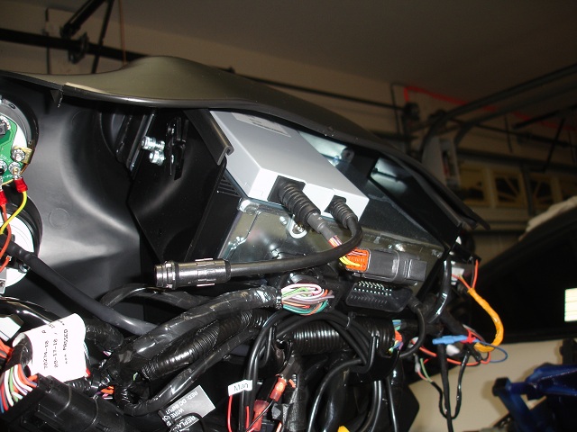
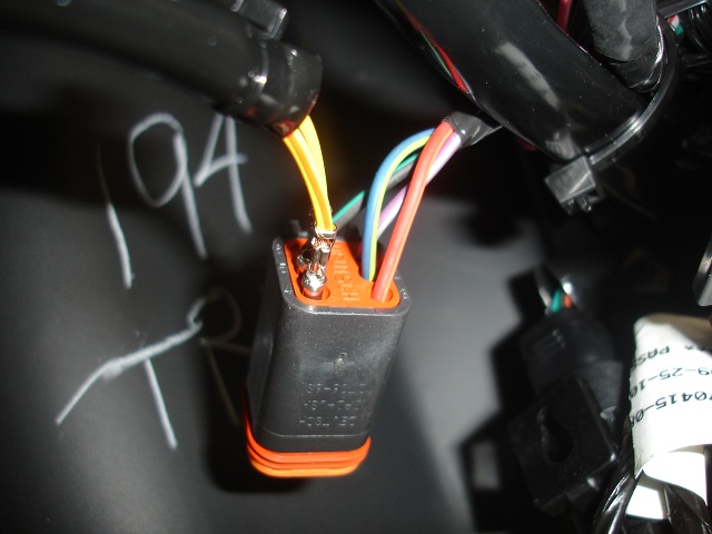
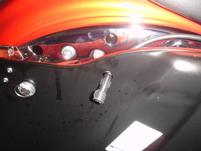
Harness in the motorcycle where the other end of the two wires go...
And, on the Road Glide Custom, the two plugs that stay disconnected... if you don't have navigation and not sure what else...
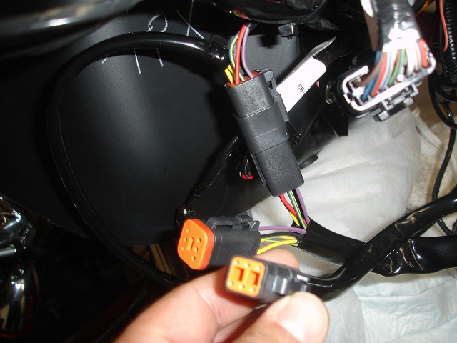
Now that all connectors are in their place, try to hold them together with tie wraps to avoid pinching any cables with the fairing or fairing hooks...

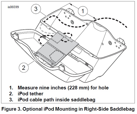
The cable to the saddlebag. Remove your seat, (I routed the cable under the center console) loosen the center console (two bolts, one in the back, on in the front). route the cable. Install the two bolts for the center console again, careful not to pinch the cable.
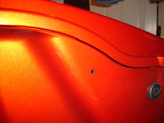
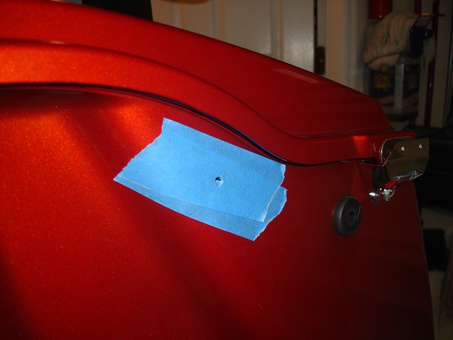
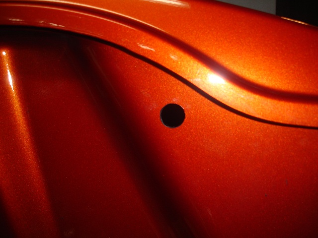
Drilling the hole to pass the cable. 16mm.
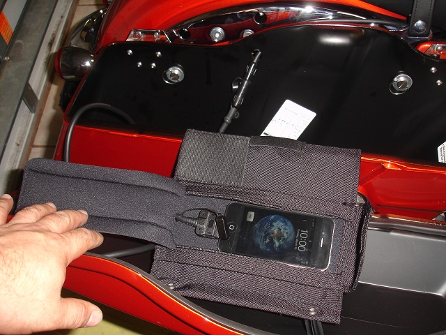

Now we are done:
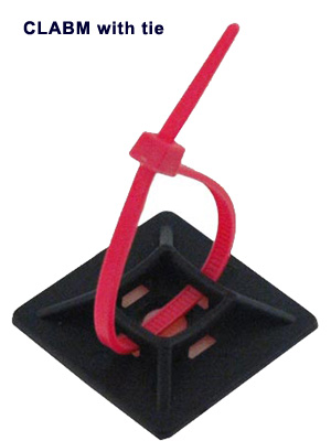
I still need to put some of those glued on cable tie dows to hold the cable against the bottom of the saddlebag. I think Radio Shack should have those. Just use the double face tape that comes with them, place a few along the side of the saddlebag (inside at the sides at the bottom). and route the cable, hold it in place with tie wraps).
Harness in the motorcycle where the other end of the two wires go...
And, on the Road Glide Custom, the two plugs that stay disconnected... if you don't have navigation and not sure what else...
Now that all connectors are in their place, try to hold them together with tie wraps to avoid pinching any cables with the fairing or fairing hooks...
The cable to the saddlebag. Remove your seat, (I routed the cable under the center console) loosen the center console (two bolts, one in the back, on in the front). route the cable. Install the two bolts for the center console again, careful not to pinch the cable.
Drilling the hole to pass the cable. 16mm.
Now we are done:
I still need to put some of those glued on cable tie dows to hold the cable against the bottom of the saddlebag. I think Radio Shack should have those. Just use the double face tape that comes with them, place a few along the side of the saddlebag (inside at the sides at the bottom). and route the cable, hold it in place with tie wraps).
Last edited by wachuko; 03-21-2011 at 11:35 AM. Reason: one more photo...
#3
03-17-2011, 09:03 AM
Extreme HDF Member
Excellent write-up and great pictures. For all of the iPod interface module theads, this is the first that I recall with pictures of the installation in the saddlebag (especially drilling the saddlebag to run the cable), and pictures of the 6B connector (where you added two wires) and 28 connector where you added three wires utilizing the 69200033 harness.
Again, excellent write-up and pictures.
Carl
Again, excellent write-up and pictures.
Carl
#4
03-17-2011, 09:16 AM
Excellent write-up and great pictures. For all of the iPod interface module theads, this is the first that I recall with pictures of the installation in the saddlebag (especially drilling the saddlebag to run the cable), and pictures of the 6B connector (where you added two wires) and 28 connector where you added three wires utilizing the 69200033 harness.
Again, excellent write-up and pictures.
Carl
Again, excellent write-up and pictures.
Carl
Sharing the photos to avoid others the frustration I went through

Grommet for the saddlebag cable hole is back ordered, so I will post a few more photos when that comes in and when I install the cable holders inside the saddlebag. Cheers!
Last edited by wachuko; 03-17-2011 at 09:21 AM.

#7
03-17-2011, 06:57 PM
Outstanding HDF Member
Trending Topics
#8
03-20-2011, 02:45 PM
Something I left out:
Link to the only install pdf I found online. Always check the version of your install instructions as a few changes have been done over the years:
HD Install Instructions
The install doc included in mine was a newer version, but it did not include the routing of the cable in the saddle bag like the one I found in pdf format.
#9
03-20-2011, 05:18 PM
Grand HDF Member
I struggled a little bit with this install....I have an Ultra classic, and wanted to route the iPod cable to the fairing lower. I did, but struggled with the idea of putting a hole in it. It worked out OK, and looks good too, so I'm happy. Plus, I did not realize until I had the pins in that I had the earlier (wrong) pinout and had to remove them, which was easier than I expected. I am really happy with it..it is a very good interface, although not without it's quirks. I have had many types of iPod interfaces in cars and they all have some little thing that bugs me.
Excellent write up and pictures!
Excellent write up and pictures!
