Dyna Glide ModelsSuper Glide, Super Glide Sport, Super Glide Custom, Dyna Glide Convertible, Super Glide T-Sport, Dyna Glide Police, Dyna Switchback, Low Rider, Street Bob, Fat Bob and Wide Glide.
Gotcha. I could have machined one in one of the Mazaks, but for me, it was cheaper to buy one when I figure in my time used to make it. It’s always a balancing act when you have to figure in what your time is worth.
It's a bushing to prevent the socket from wobbling and damaging the shaft. Some of the sockets have a reduced inside diameter instead.
So you slide the bushing over the very end of the shaft and it fills the inside diameter of the socket so there is no room for wobble? If so I could just make a bushing. Though I would think if you're careful you wouldn't have an issue.
That's correct. Removal with an impact is simple...no side load. Applying the correct torque on reinstallation without side loading the socket badly is a bit trickier.
Head bearing race's are out and the new race's are installed. Jims Tool 33071-73
Edit
I wrote a long step by step on removing the race's with the Jims tool because i couldn't find anything on the web on how to use the tool. Even the Jims site had nothing on how to use it. On HD Forums i saw posts with people asking how to use the tool, so I figured I would document the procedure thoroughly. I went back and read it. If you don't plan on using the Jims tool, you probably want to skip all the reading because you would probably have a better time watching paint dry.
______________________________________________
Using Jims Tool 33071-73 Head and wheel race removal tool instructions.
I First I tried using the method I left in the link. I only tried it on the top race and I got it to start coming out but it took a lot of pounding. Harley said don't add heat but every independent I spoke with said add heat, so if you're going to try it, you decide.
https://www.google.com/url?sa=t&source=web&rct=j&url=https://m.youtube.com/watch%3Fv%3DbjQwKfzyNLM&ved=0ahUKEwjjpPn6quvbAhUDC TQIHVQwCEwQwqsBCCAwAA&usg=AOvVaw3M5Y6Q1qN4kd0ewpUf GfDS
Today I used the JIMS tool # 33071-73 that I was loaned. It took me a few calls to the loaner to figure out how to use it, but after he explained it the job was a breeze!
If you use the tool, when you look at the outside of the two die's they have a taper and a lip. The taper on the die's matches the taper of the inside of the race and the lip catches the bottom of the race.
So you put one die in and then the next. You have to hold them in place or they will fall out. Next I took a flathead screwdriver and stuck it between the gap in the two die's. You want to go to either far end of the gap, turn the blade of the flat head making the other end of the die's touch. When you look down at the gap it now should look like a triangle. You then take the wedge with the posts facing down and slide one side into the gap. After the post is in the gap, you take your flathead and open the gap up on the other side so the post can slide across to where the whole in the wedge is directly in the center of the die's. You then take the drift and insert it through the opposite end of the head opening and push it through the hole in the center of the die's. you hold the die's and post in place with your fingers while doing this or else everything would just fall out. After this is done the drift now has the die's spread tight so the lip's on both die's are locked in underneath the inside ledge of the race. You then use a 2 pound mini sledge to tap the race out. The race's come out very easy using the tool. You don't have to use much force with the 2 pound at all. Just make sure to keep the drift centered and true. Keeping the drift centered and true during race instalation is especially important. If your tool and race alignment is off during install the race will dig into and gouge the side's of the head bearing cup. You do not want that to happen or else the race will bind up and won't go in at all. If one side of the race is going in faster than the other, stop, remove the race and start over, trying better the next time to make the race go in evenly on your next attempt. If you gouge the wall the race, the race is going to want to naturally follow the path of the gouged wall and it will make it much harder to get the race to go in evenly and true.
After you remove the old race's clean the entire head out with parts cleaner and run a rag through the head until it's clean. Be sure to clean both the top and bottom race lip's of the head really well. Then take grease and coat both the heads top and bottom race lip and the race's themselves. You don't have to add gobs of grease but enough to aid in the new race install. You don't want metal on metal.
My bike is a 2012 FXDB and it doesn't have a zerk fitting. While I have the head open I am going to install one. Harley heads use to have zerk fittings but they did away with them on the Dyna's. I belive touring bikes still have zerk's. The custom builder that I met, who is pretty well known in the building circuit and who has 40 years experience in building and servicing bikes, recomended I add one. I was already thinking I was going to, but he reaffirmed my belief that one should be there.
If you decide to add a zerk be sure to look into your head first and make sure it has no openings in it leading into the frame. Many models have openings going into the frame, so make sure you check before you drill a hole for a zerk fitting.
If your head has openings, but you still want to add a zerk, you have to get a piece of thin walled pipe that will fit the inside the center portion of the head in between both race cups. The pipe will seal the holes going into the frame so the grease you pump in stays in the head only.
All of the Harley's I have seen zerk's on, the zerk was located just above the lower down tube at the right rear of the head. Obviously check for clearance issues first before you drill into your head.
I think that's about it. I will document my zerk installation tomorrow. I don't know a ton about zerk fittings so I plan I doing some reading before I buy one. They are a machined part so like anything else, you probably get what you pay for. Maybe I'm wrong and the zerk's they sell at big box part store are just fine. I will soon find out.
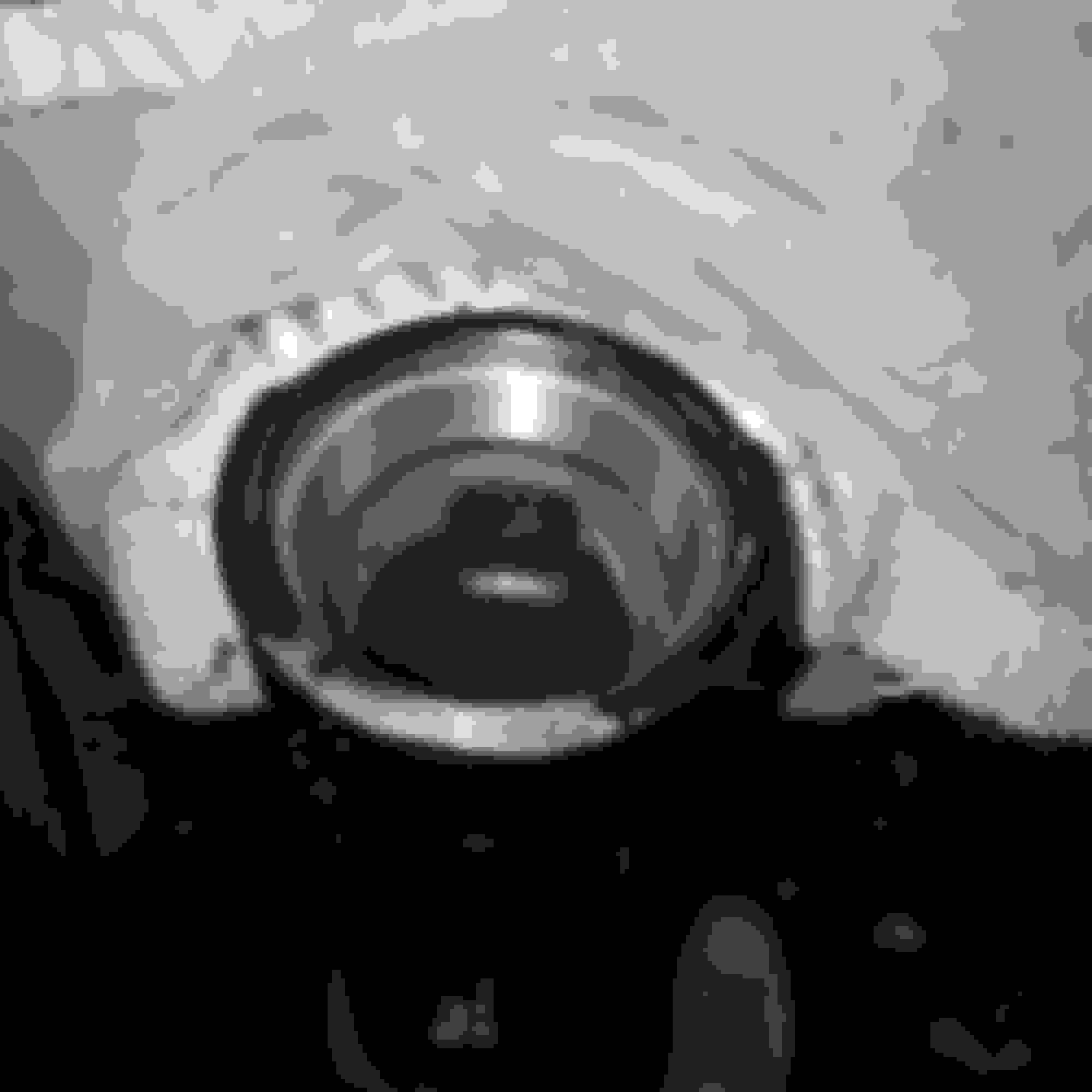
Pic#3
Here is the Jims tool 33071-73. To the right is how the dies and wedge should be lined up inside the old race or the new race durning removal and install. I highly remomend using this tool. It makes removal 100x easier. I also saw a video on youtube where a guy was using what i think was a plasma cutter to cut his old races out. So apperantly you can do that also.
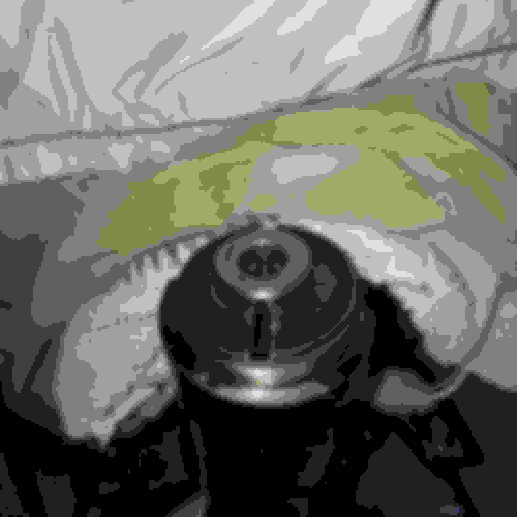
Pic#2
Here is the die's and wedge placed inside the race correctly.
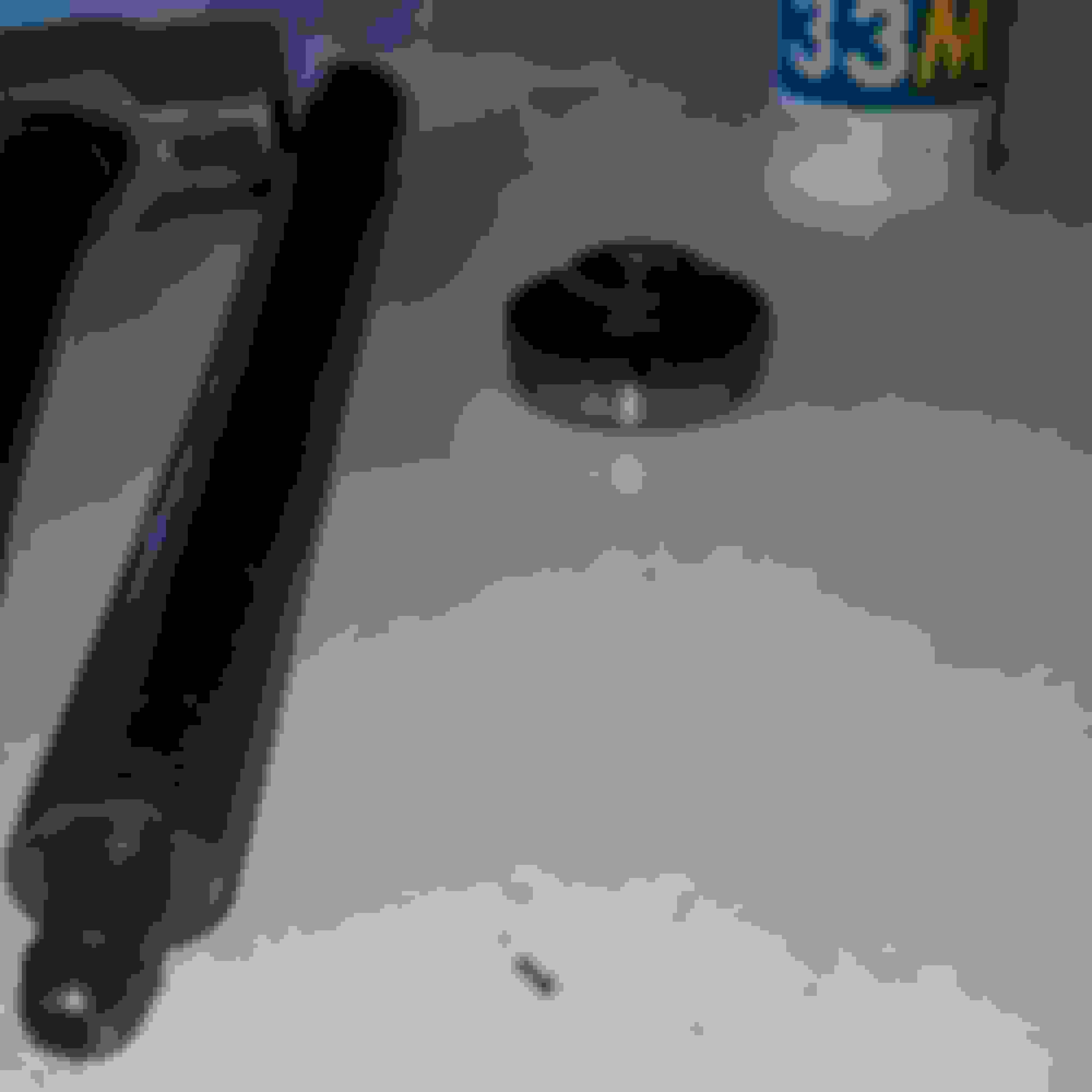
Pic #1-
Here is the Jims tool 33071-73 and all its parts. See how the die's have a tapered edge. So for example, if you're removing your top race the die's would be flipped upside down so the taper of the die's and the tapper inside the race match.
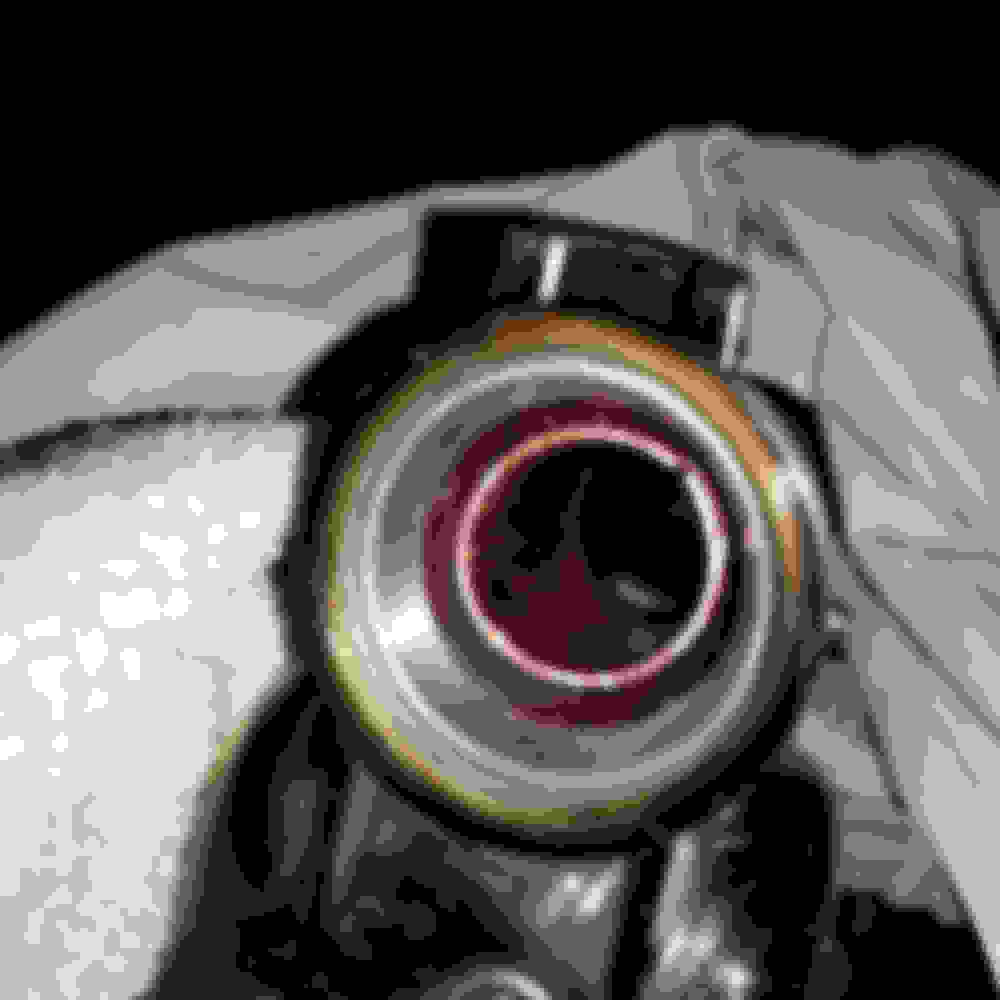
Pic#4
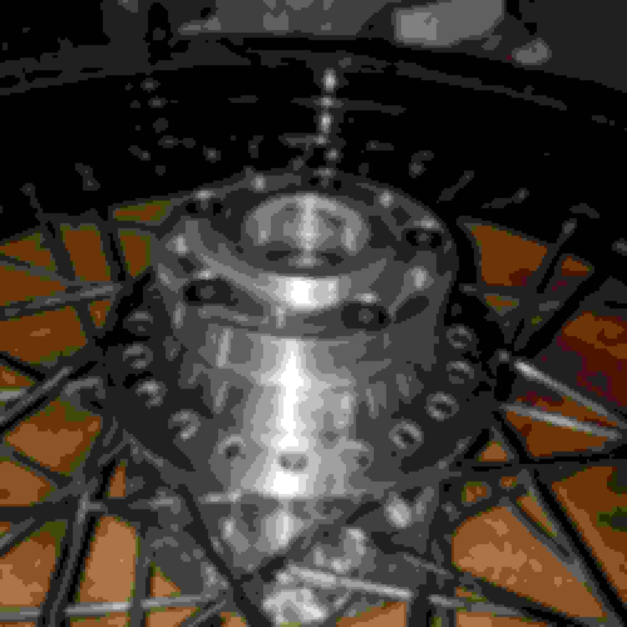
Here is the drift inserted through the bottom of the head. I didnt have a cameraman, so if i hadn't inserted it yet my right fingers would be over the die's and wedge to keep them from pushing out. I would then insert the nipple on the end of the drift into the bottom whole of the die. Once the drift is in the die hole, you have hold the drift perfectly center and straight so the race gets driven in evenly. If the race is going in correctly, you should only have to give forceful taps, you shouldn't have to pound.
Pic#5
Here is the new race installed. Remeber to put a liberal amount of grease on both the race and the race lip inside the head. The top race went in with no problem at all because it's much easier to keep the drift true coming from the top. I had to start and remove the bottom race three times before i got it to go in straight. It went in deeper and straighter after each attempt. Remeber do not force it. Just stop, remove the race and star over. Do not gouge the inside of your race cup.
Last edited by Valleyofthegun; 06-24-2018 at 01:53 AM.
I spoke too soon when I said I didn't have holes leading into my frame. Sure enough there is two small square openings at the back lower half of the neck that lead into the frame.
I would assume all Dyna's have these passage ways or at least all 06-17, and possibly 2018 as well.
If you have the passage ways and still want to add a zerk fitting, you have to sleeve the lower half of the neck with a 1-1/4" copper coupling to block the passage ways.
I tried 1" and it was too loose. I tried 1.5" and it was way too big. The circumference of a 1-1/4" copper coupling is still just barely too large to fit in the neck with out pounding the hell out of it. I ended up breaking out the Dremel tool with a cutting wheel and I cut a 1/4" wide slot out of the coupling so it could close in on it self. It looked like a cuff style bracelet after I was done. I greased it up and tapped it up inside the neck, and i got nice snug fit.
I used a center punch to mark the exact spot i wanted to drill. The zerk's I bought were 1/4"-28 so I used a 3/32 drill bit to get the hole just barely started and 7/32 drill bit to drill the rest of the hole. I then I tapped it with a 1/4-28 tap. I got the tap started, turned it a bit and backed it out, turned it a bit and backed out, taking extra precaution not to snap my tap off in my neck. Taps snap very easy so do not force it. The zerk's I got were 11/16" ball check but I'm going to try to find one that is a little longer on the threaded side because I want it to go all the way through the copper sleeve. Right now it is just barely poking through. I doubt the sleeve could turn on me seeing who tight the fit is but I figure if I can find a longer one of will put it in.
I put my zerk on the bottom because 1, i had to lock the sleeve in place and 2, because all the harleys that had zerk's from the factory that i saw had them at the bottom in the general area i mounted mine. Looking at the picture now i woukd think the zerk would be better at the top so the grease didn't have to fight its way to get all the way back to the top bearing. Hopefully it pushes up before it starts pushing out.
I could have trimmed material off the end of the coupling so it did not hang down so much but it is way above the race so i figured i woukd leave it so there is something to grab on to in case it ever needs to come out.
All in all the job was a pain in the *** but only because I had to get the sizing of the sleeve correct. After I figured out the 1-1/4 coupling would work best, the job was easy.
So reading through the forums I got mixed veiws. Many said adding a zerk is a waste of time and unnecessary because there is no real load on rhe neck bearings. Others said it was a very good Idea. My reason for doing it is so I can lube my bearings but also because I noticed surface rust on the stem of the trees I pulled off the bike and also on the wide glide trees I'm replace them with.
Triple trees, rebuilding the forks and Race Tech gold valve Emulators
I was going to rebuild my forks today but I decided to wait until tomorrow so I can speak with Race Tech. I was under the impression that the kit came with aluminum and pvc that could be used to fabricate the preload spacers. My kit only came with a stick of pvc. I know RT says pvc is plenty strong to use as a spacer but I rather use aluminum if I can.
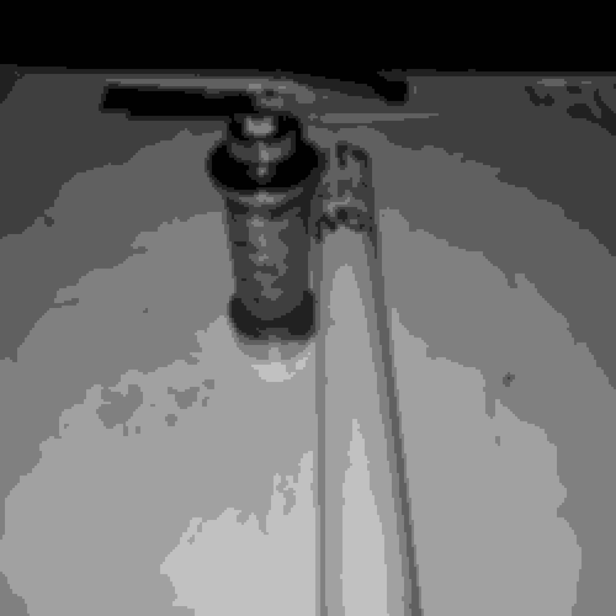
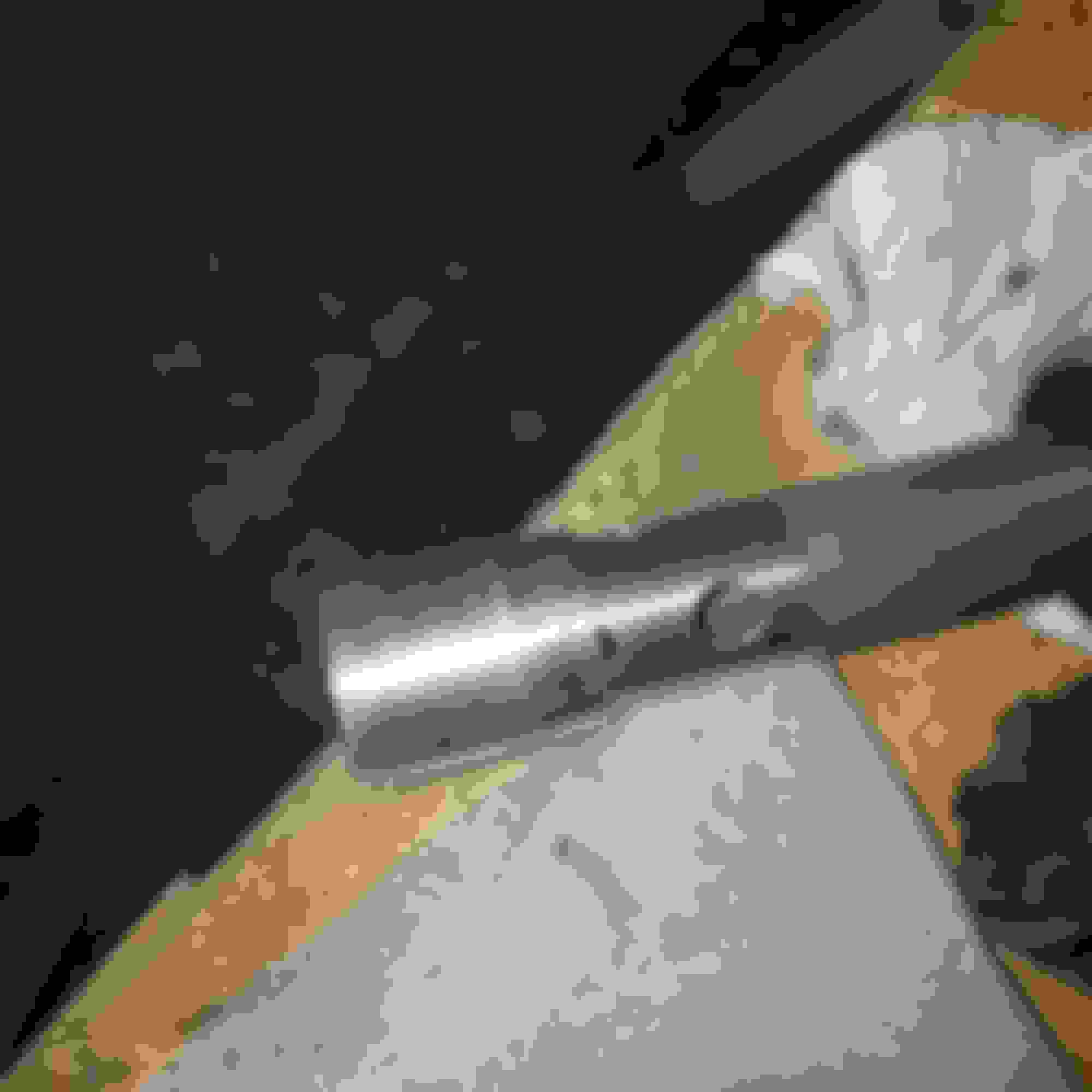
Anyway, it wasn't a total waste of an evening. I got my hi-tech fork seal driver tool made, as well as my mainshaft sprocket wrench, for when it comes time to replace my 32t with a 30t transmission pulley.
I used a 6\" piece of 2" inside diameter thick walled galvinized pipe i had laying around and i bought a 2-1/4" socket from a local autoparts store for 25$. Mark the owner of DunnRite Bikes did the welding for me, thank you Mark.
I finally got the Emulators installed and the forks rebuilt with all new seals and bushings. All I have to do tomorrow is add oil and I'm done. This is my first experience ever working on forks of any kind. Forks have a lot of parts and are complicated enough by themselves. Then you throw Emulators in the mix and it was enough to overwhelm me at times. I am the type of person that needs to grasp exactly how something works before I feel comfortable doing the work. I ended up having to reach out to Mark from Dunnrite bikes so much so that I felt like I was being a burden. I definitely owe him a few cold ones. Needless to say he was patient, answered all my questions and I finally got the job done.
Much of my confusion could have been avoided if I would have taken more pictures and documented the orientation of each part better as I took them apart.
With the Emulators you have to bore out the two exsisting holes in the dampening rods to 5/16" and drill four more 5/16" holes. I put two above the exsisting holes and two below the exsisting holes. In highensight, I should have drilled my four added holes above the two factory holes because when you put the " oil lock/Fork stop" back on the dampening rod, it partially covers up the two bottom holes. I was told that it won't be a problem and to not drill any extra holes. The point of drilling the holes so large is to allow oil to flow through them without any resistance, thus letting the Emulators do all the work.
I'm not going list all the issues I ran into. I'm only going to list the correct orientation that the parts should go from the bottom of the slider to the top and the orientation of the oil seal.
From the bottom to the top for 49mm Showa forks only. Parts and orientation vary from each model of fork.
1- screw
2-washer
3- slider
4- oil lock/Fork stop. It fits over the end of the dampners like a cup
5- lower rebound spring
6-dampener. You can replace the plastic ring around the cup, if you're adding new seals.
7- Aluminum Emulator adapter. The adapter ensures that the Emulator sits and stays centered properly over the cup of the dampener.
8-Race Tech Gold Valve Emulator. Spring side up.
9- upper main spring
10-Flat washer on top of the main spring
11-Pre load spacer. I cut the stock pipe spacer down but RT also provides a stick of pvc that you can use. Pvc makes for a quiter
fork.
12- Second flat washer
13- fork cap.
Now for the seals on the outside of the fork tube.
1- bushing
2-large flat washer/bushing protector
3- oil seal. The outside perimeter has a beveled edge on the top and it has a ledge that sticks out just a hair on the bottom. You have to put the side with the ledge facing downwards. Refer to the pictures to see exactly what I'm talking about.
4-lock ring
5-rubber dust cover
6- Aluminum fork dust cover.
That's it. If you're running Emulators you have to get with RT to get your individual specs on how much preload to add to the emulators and to the main springs.
Here is where the oil lock/fork stop is covering the bottom holes i drilled. RT says it will not be an issue so i hope they are correct. If you drill yours only drill above the factory holes.
If you look close, the outer rightside of the fork oil seal, it has a slight ledge that sticks out. The side with the ledge faces down during installation.
Last edited by Valleyofthegun; 07-01-2018 at 03:54 AM.
I converted my mid glide front end to wide glide by using a set of FXDF trees and a spacer kit from Hawg Halters.
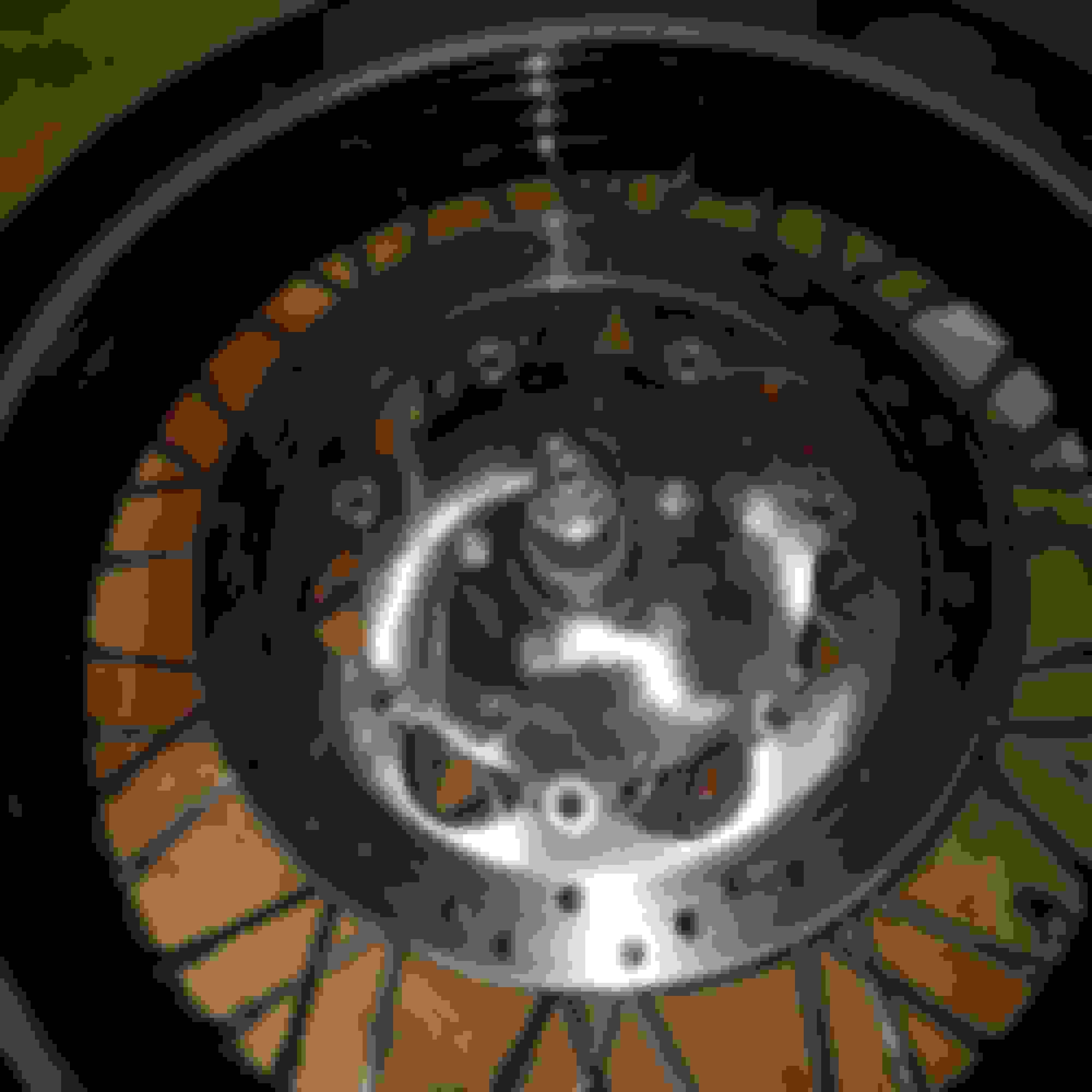
I noticed after I installed the spacers that the gap between the hub and spacer wasn't even all the way around. I ended up having to disassemble and reassemble it three times before i was able to get the gap even. I used a rotating torque pattern everytime so all I can think is that there was some flex in the spacer that needed to be worked out
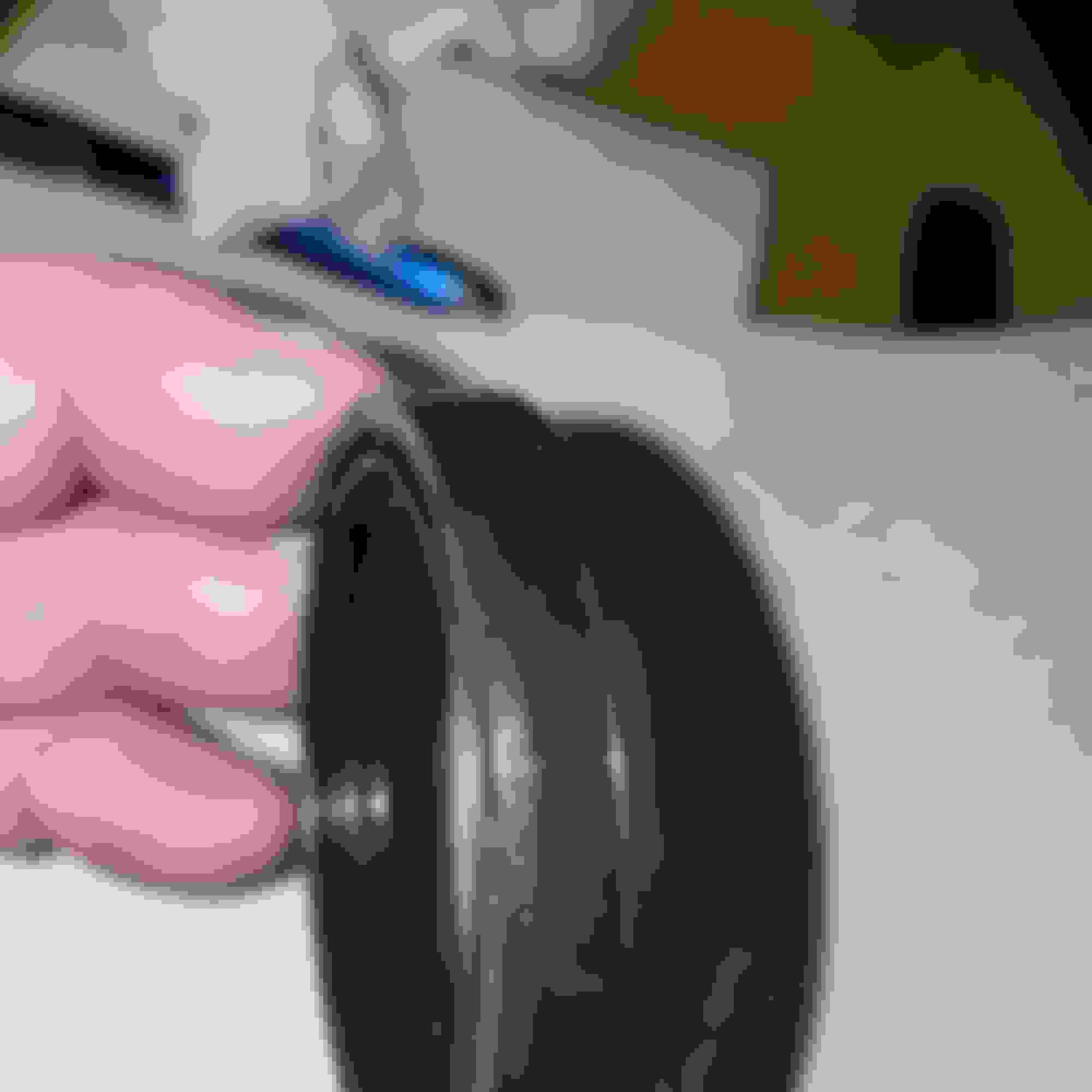
I had some scratches on my rotor and the used axle that I bought was pretty rough. Also my front wheel was covered in brake dust and other grime. While the wheel was off, i scrubbed it spotless using a solution of simple green and white vinegar. It got every bit of grime off. I ended up using mothers polish to buff out the scratches. It also worked great.
I held off on mounting the brake caliper because I noticed I need new pads. Tomorrow I will be replacing the pads and I will be getting my bushings, risers and bars mounted.
My front turn signals are currently part of my mirrors. The right mirror was damaged in the accident. Instead of paying HD another 280$ to replace them, I am going to reroute the signal wires and mount the signals on the trees or fork tubes. Hopefully pulling the pins from the connectors won't be too much of a PITA.
Until tomorrow!
EDIT
I just spoke with Hawg Halters.They don't know why I had the issue with the gap. Their rotor spacer gets torqued to the same spec that HD recommends for the rotor bolts=24 FT LB.
They did tell me that they advise using blue thread locker on the bolts. I now have to tear everything back apart to add blue thread locker. The HD manual does not specify using any thread locker. If Hawg Halters wants you to use blue thread locker, you would think they would supply instructions specifiying to do so.
That would make too much sense though. Well this freaking blows, another hour or so of added work all because HH can't **** the change loose to print up simple instructions. I don't even care if they are printed, write them on the the damn box for all I care but provide them. Fu#%
Fresh new gloss black powder coat on the new wide glide front end. I have to say, i wish i would have stuck with the matte black finish. I don't know if gloss scrathes easier or if the scrathes are just more noticeable.
Here is one of the tar filled scratches that i worked out using mothers polish.
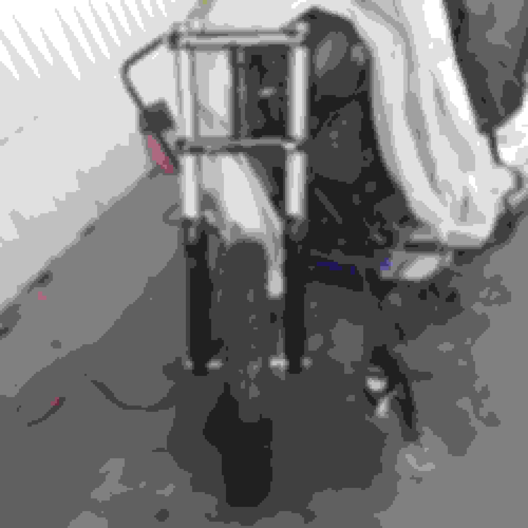
Here is the Hawg Halters rotor Spacer. You can see the gap between the hub and spacer that i am talking about bot being even. Hopefully i got the issue fixed for good.
Here is the new WG front end with the wheel mounted. You can also see the wider wheel spacers that Hawg Halters provided with the mid to wide glide conversion kit.
Last edited by Valleyofthegun; 07-03-2018 at 08:44 AM.
 06-23-2018, 07:58 PM