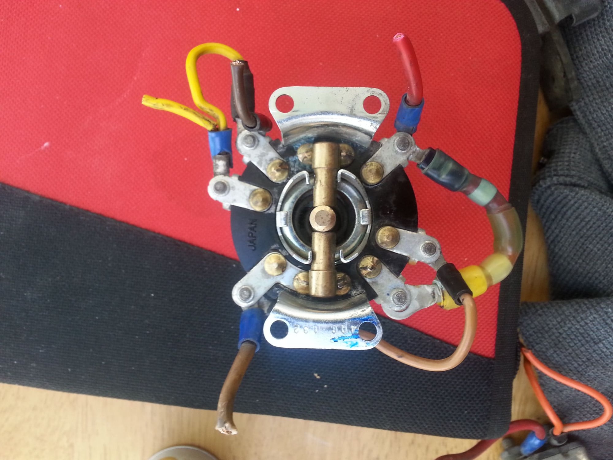
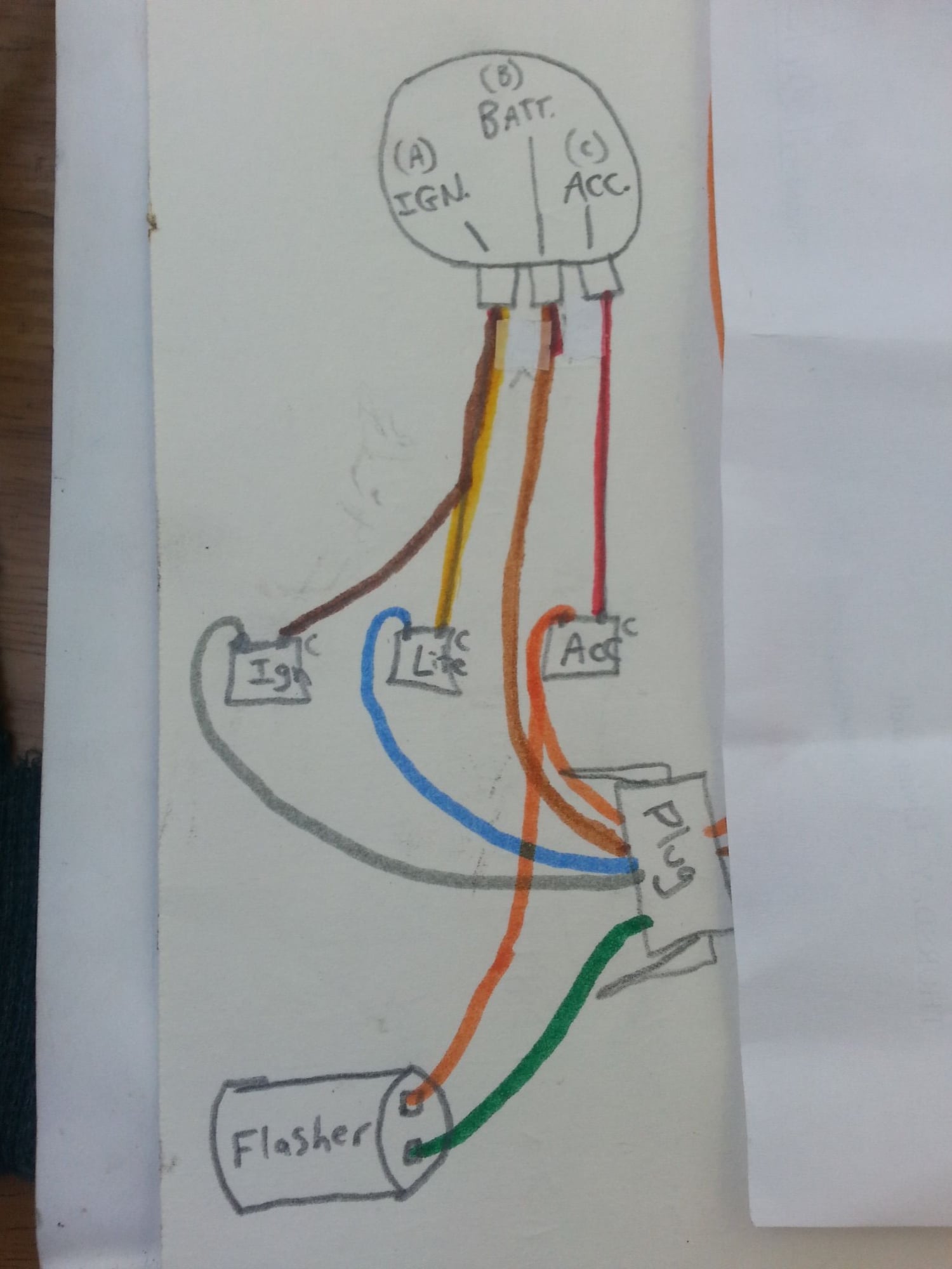
6 pin to 3 pin ignition
#2
Check the wiring diagrams for an older Softail and a later model that uses the modern switch.
The old switch is fed by a wire from the main circuit breaker.
The switch feeds the accessory breaker, the ignition breaker and the lighting breaker, so that is a total of 4 wires connected to the switch.
Terminals B and C on the switch are connected by a short jumper wire, so that the headlights are on whenever the ignition is on.
When using the three wire switch, you could install a short jumper wire between the posts on the ignition and lighting breakers (the copper colored posts); doing that would eliminate the need for one of the wires between the switch and the breakers.
So...with the three wire switch...
Wire from switch to the main breaker output post (not the copper colored post).
Wire from switch to the input side of the accessory breaker (copper colored post).
Wire from switch to either of the copper colored posts (input side of breakers) on the jumpered ignition/lighting breakers.
Hope this makes sense...it`s late and my eyes are tired from looking at faded out wiring diagrams...

Last edited by Dan89FLSTC; 01-14-2014 at 04:28 AM.
#4
That is the old Softail switch.
I edited my previous post, the wire colors were for a newer bike. You will need to check the colors on your wiring diagram, or just trace where the wires go...
I edited my previous post, the wire colors were for a newer bike. You will need to check the colors on your wiring diagram, or just trace where the wires go...
Last edited by Dan89FLSTC; 01-14-2014 at 04:30 AM.
#6
#7
Let me try this one more time....
The wire from the main breaker goes to the center terminal on the new switch, that is where the power goes in to the switch.
The wire from the accessory breaker copper colored stud goes to one of the outboard terminals on the switch.
Install a jumper wire between the copper studs on the ignition and lighting breakers, and then connect a wire from this stud to the other outboard terminal on the switch.
You can figure out which outboard terminal is which by using an ohmmeter, or just connect them and see what comes on when you turn on the switch, if it is wrong, just reverse them.
Trending Topics
#8
i am hoping this will pertain to the thread so i am putting it here as knowledgeable folks are already commenting,....
I recently had a mech put a new 6 pin, 4 position ignition switch in my bike. (75 elctra FLH).positions were 1 left, center(off) 1 right, and 2 right. It replaced a worn out one of the same kind. my problem is that before when i turned my switch to the first position left, i would get acc power but could not start bike. 1st position right was power, starting ability, and no lights, 2nd position right was power, starting ability, and with lights. so i could basically cut my lights out 100% and ride on pos. 1 right.
now with the new switch i have nothing 1st pos. left, and 1 and 2 pos right i have full power, starting ability and lights on on both switches. he told me that he did it exactly like the other blah blah of course. i just took my bike and went on home instead of arguing. i have found diagrams online but they are really not legible and have no color schemes. any thoughts? (and i ordered the manual already) just picking brains.
ty
Headzup
Last edited by Headzup; 01-17-2015 at 08:40 AM. Reason: more detail and spell correction
#9

im doing this same thing you are attemtping as you can see these are the wires I snipped from '89 softail switch and im hoping these jumper wires wont be needed. I omitted dash/dummy lights since mine is a bobber project
pictured below is the main clip plug, wires from it either run to the flasher for signals. than to ignition, lites, acc relays which look like little silver rectangles. from the relays they run to the 4 wires I cut from the old switch on my 89 heritage. Rest of the wires already had connections or were tied up elsewhere.....I've never done this but am going to try do what you're doing n go to a newer 3 pin switch.
Last edited by IndianHarley; 01-26-2015 at 07:09 PM.
#10

Let me try this one more time....
The wire from the main breaker goes to the center terminal on the new switch, that is where the power goes in to the switch.
The wire from the accessory breaker copper colored stud goes to one of the outboard terminals on the switch.
Install a jumper wire between the copper studs on the ignition and lighting breakers, and then connect a wire from this stud to the other outboard terminal on the switch.
You can figure out which outboard terminal is which by using an ohmmeter, or just connect them and see what comes on when you turn on the switch, if it is wrong, just reverse them.
The wire from the main breaker goes to the center terminal on the new switch, that is where the power goes in to the switch.
The wire from the accessory breaker copper colored stud goes to one of the outboard terminals on the switch.
Install a jumper wire between the copper studs on the ignition and lighting breakers, and then connect a wire from this stud to the other outboard terminal on the switch.
You can figure out which outboard terminal is which by using an ohmmeter, or just connect them and see what comes on when you turn on the switch, if it is wrong, just reverse them.
Last edited by IndianHarley; 01-26-2015 at 03:12 PM.


