1). On my wiring schematic I show numbers 54 and 55 as a turn signal pilot light. Don't really know what that is or where it goes. Are there little lights on my dash to tell me when my turn signals are on?
2). Front and rear terminal boards? Don't have anything like that on this bike. I see that I can buy them in the JP catalog. Where did they go?
3). On my left handlebar switch I have a horn button and a left turn signal button. There's also a headlight button, so I'm guessing that must be my highbeams. on the right hand switch, number 56 is labeled "stop light switch front." I'm guessing that's my kill On/off yes no? Maybe not� Because there is a wire from that button it goes to the taillight.
4). I cannot find a starter relay anywhere on this bike. The guy that had it before me started it with a screwdriver by touching the solenoid terminals together. did I mention this thing was a rat-bike? Where would a starter relay mount on this bike?
5). How do you know what gauge wire to use?
Sorry about numbering all of these. I know it's kind of ****. But I thought it might help.
1. Original equipment used pilot lights that were attached to the back left and right side of the headlight nacelle.
2. Original equipment used a terminal board that mounted to the upper right portion of the top tro[ple tree (as you sit on the bike). A second was located/mounted on the seat post down tube behind the coil.
3. The kill switch and the stop lamp switch are not the same. The kill switch cuts power to the bike, the front stop lamp switch is tied in with the brake light switch and is activated when you pull in the front brake lever.
4. Original equipment used used a starter relay that was attached to the bottom of the battery box and covered with a chrome cover.
5. Can't answer the last because I am unsure which wires you are referring to.
Awesome...thanks pansforever! That pretty much answers it. I'll figure this thing out, now.
#5 was a general question referring to the schematic. By looking at the schematic, how can you tell what gauge wire to use? Maybe it's covered elsewhere in the manual. Using too large a gauge won't hurt, will it? I know too small will.
You should be good with 14-16 ga wire for the most part. Obviously the battery cables are heavy duty as are the two main ones running off your solenoid.
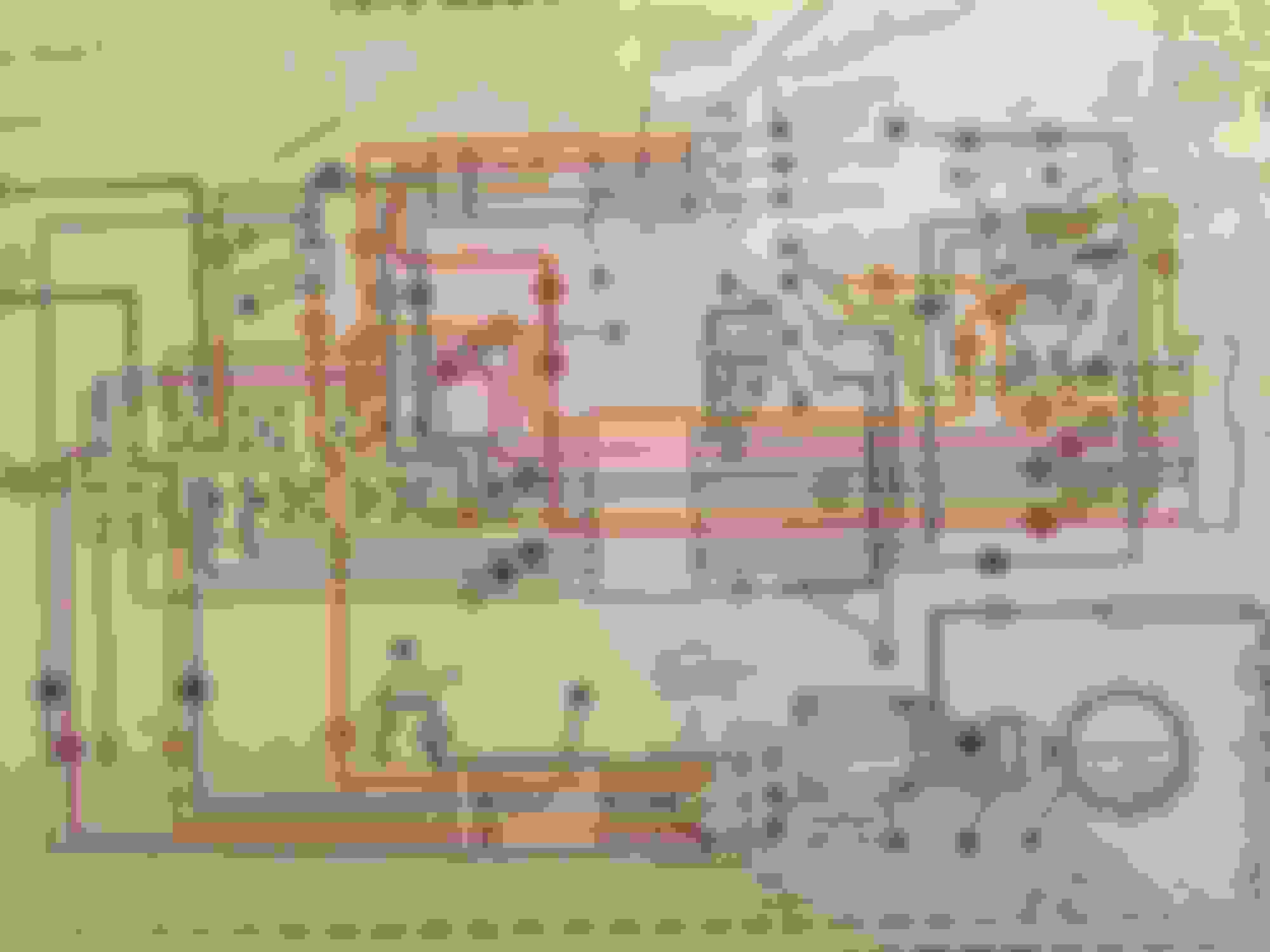
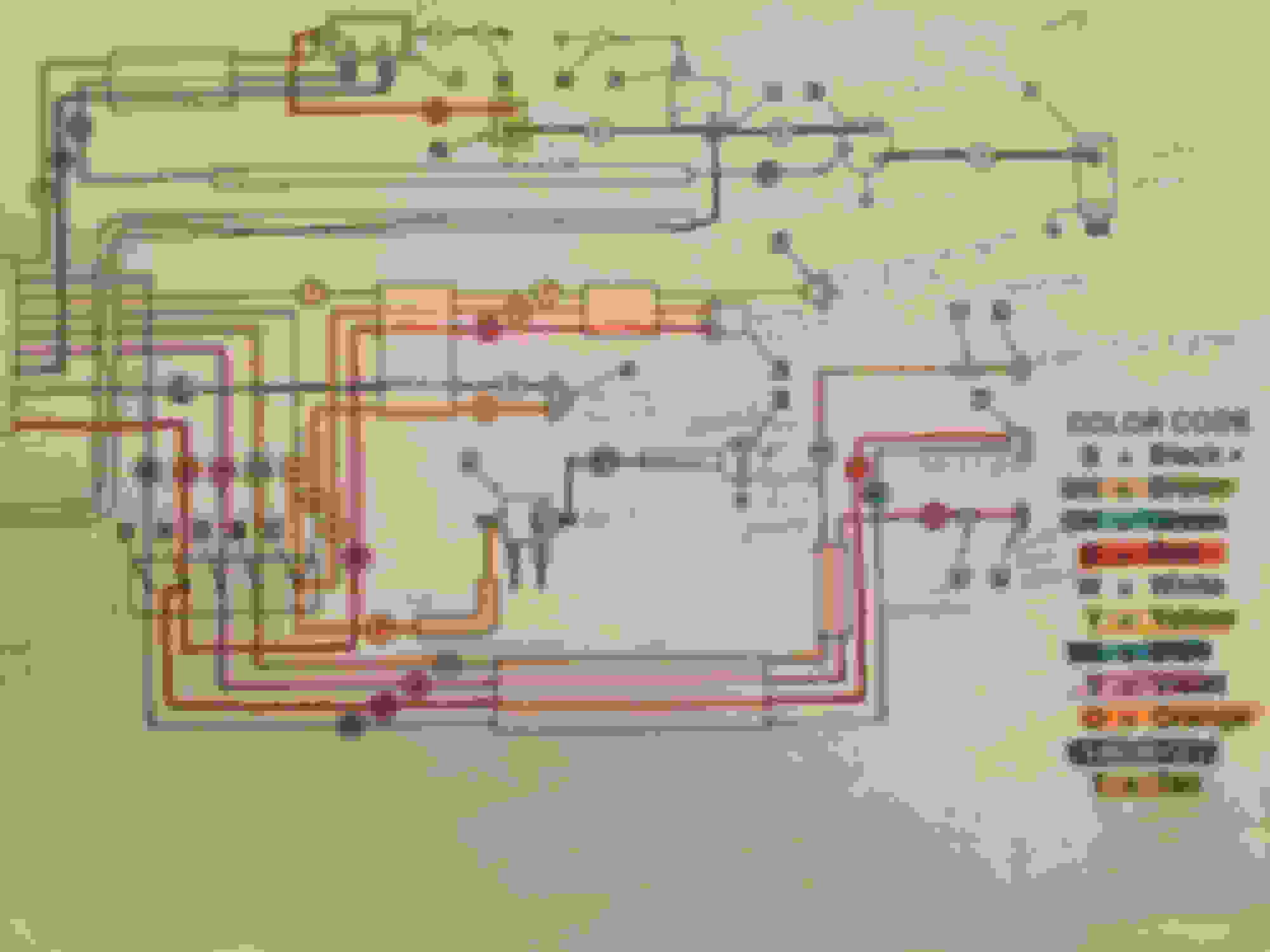
You going to try and go back to stock wiring diagram or customize? I will be home tomorrow night and can throw up a couple of pics of some wiring diagrams if not going back to stock.
If you run stock, be sure to get the service manual.
And I suggest taking the diagram to a place that can enlarge (like really big) your diagram so that you can post it on the wall while you are doing the wiring. Use colored pens to correctly identify/ trace the wires on your diagram and match it to the wire you are using.
FLH models used 3 circuit breakers that were mounted under the dash plate (FX models mounted the breakers on the front portion of the rear fender). And on FLH models until 1976 they used a 'fusible wire' instead of a 30 amp breaker off the + side of the battery. Wire in the circuit breaker and not the 'meltdown' 22 ga wire.
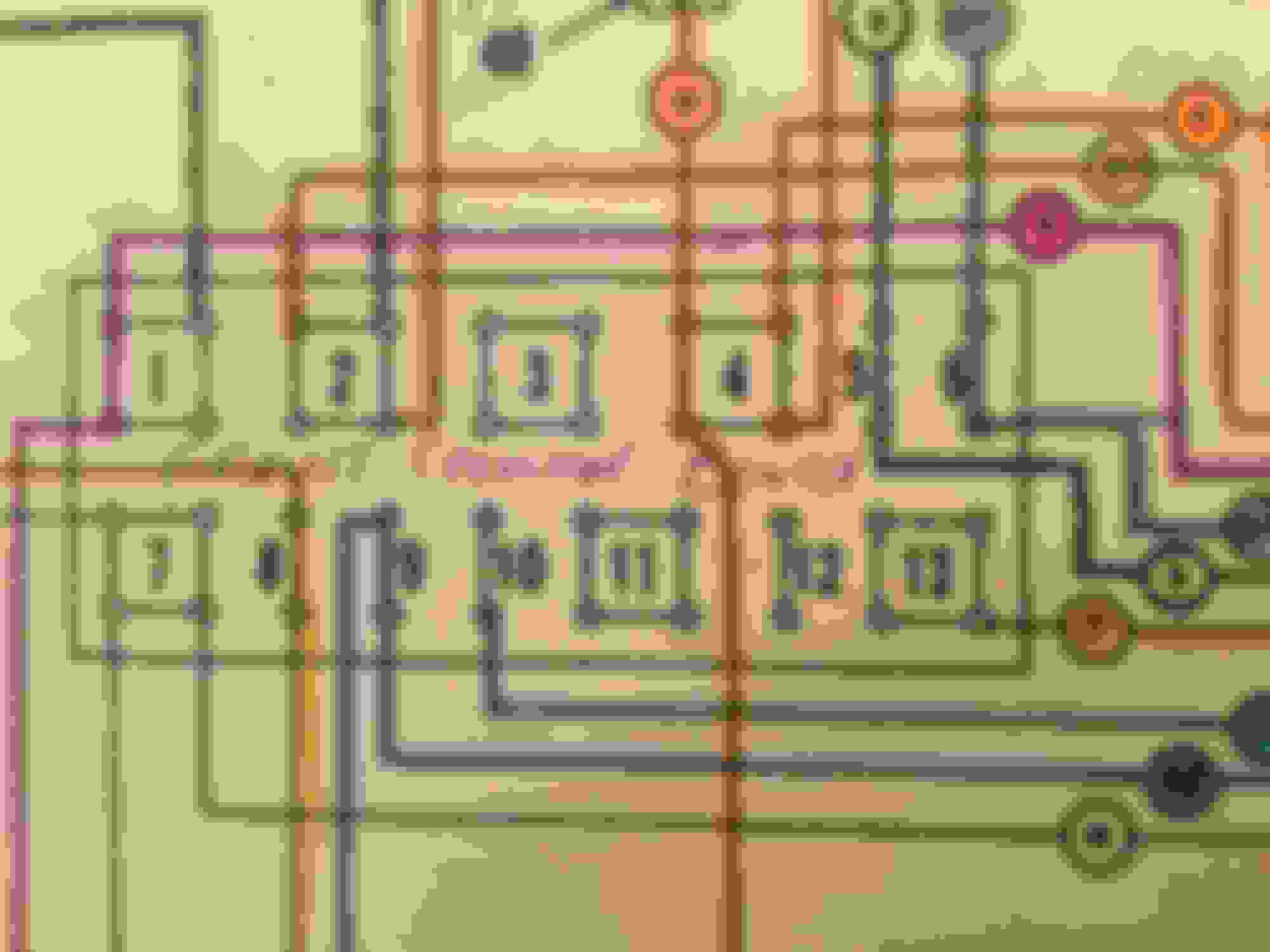
The first two terminal boards on that link are the ones I think I need, rear and front, respectively.
Just a couple things that are a little bit confusing. The original schematic for a 1972 FLH shows 13 numbers on the terminal board. The JP board only goes to 11. But I think they are the same boards and here's why: The schematic shows 40 pin sockets and the terminal board from JP has four rows of 10 sockets, making 40 sockets.
The thing I don't understand is what the terminal board actually does. Is it like a busbar in an electrical box? Do all those terminals have common power? I think they do because the schematic actually shows one wire going in which pulls power from the ignition switch and it appears that all the accessories which tie into the terminal board pull power off that one common.
Do I need some kind of terminal to push into the terminal board? I know there's a little pin tool to make removing the pins way easier.
I'll be home tonight so either tonight or tomorrow I will get the correct names for the connectors for each. Only screws things up if I don't get it correct.
FYI, if you are going stock wiring, if you look on the flea, they sell wiring harnesses, even color coded correct for the most part. Working on a buddy's 75 FLH. He got his on the flea and most of the connectors were attached.
And yes you are correct, the first is for the rear; the second for the front. And all these are are junction blocks, basically get juice from one end of the bike to the other
Pretty sure this is the terminal board I need for 72 FLH. EVEN though schematic shows 13 numbered positions and JP terminal board only shows 11, I don't know if it matters because they both have 40 slots.
So I have a couple questions . Should I just put the appropriate wire into the same location on the schematic as it would go on the actual terminal board?
Look at the close up of the terminal board on the schematic.
So for instance the violet wire goes into the lower left-hand position marked number one on the terminal board and then it also comes out number one in the upper left-hand position. Do I just strip the wire and stick it into the terminal board? Or is there a connector?
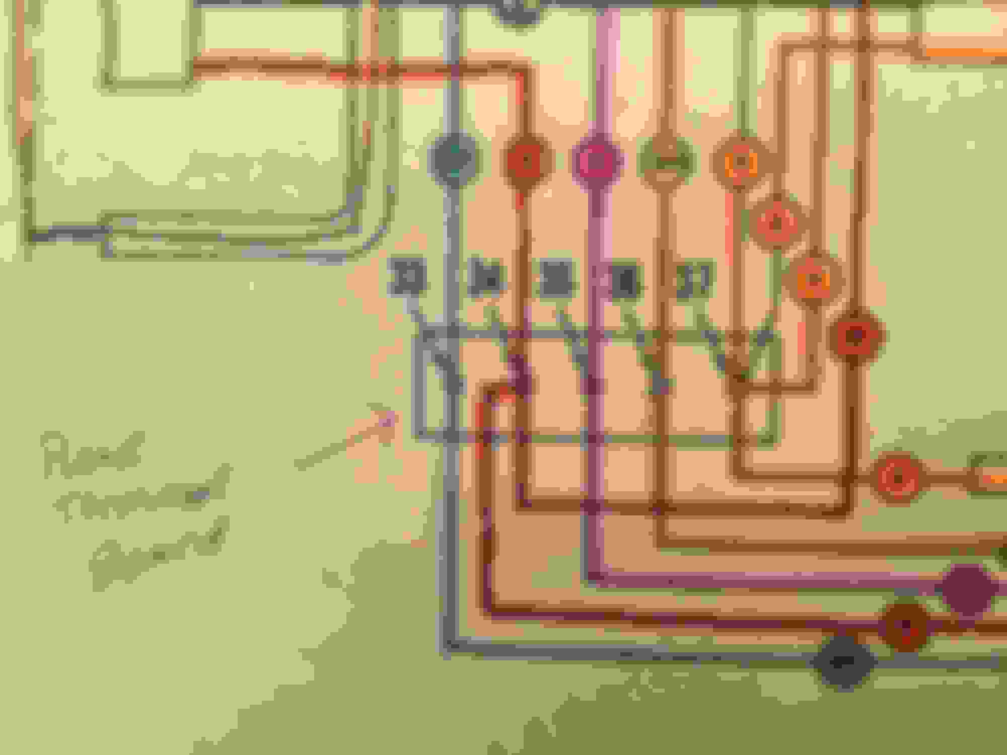
Now on the rear terminal board each terminal seems to be insulated from the others. However there are two terminals, one that has two red wires at position 34 and one that has three orange wires at position 37. Do I need the terminal board or can I just use a connector for each wire and on terminals 34 and 37, just whip them together?
i'm still not 100% clear on what the function or the purpose of the terminal board is. Is there a way to do without it and still have close to stock wiring?
In an earlier post,PANZ4EVER mentioned there were three fuses under the dash plate. I don't see those on the schematic. I do know that JP sells a block with 3 fuses in it. Any ideas?
Last edited by Bill wallace; 10-12-2016 at 05:54 AM.
Bill first of aplogies for the late response (been getting back to normal catching up on things now that I am back in town).
1. Re: the circuit breakers....my bad. The only one for FLH models was the one running off the battery + side. They used additional circuit breakes starting in '74 for FX modles but that was not added to FLH models until 1976.
2. RE: your front terminal board. Your 72 has 13 places for the junction; in 73 that dropped to 11. That said there are 3 terminal spaces that are not used on yours. It should not be a problem to use the latter as long as you have the the space to hook up the connectors. From a quick look....the later "3" is your "4", the later "4" and "5" are your "5 & 6". Seems like it would work.
3. Re: front terminal connector. It will be a smaller version of this...not sure of the proper terminology but I always call it a spade connector. Not sure what you have for electrical stores in your area but out here we have a Frys electronics. take the terminal board with you so that you get the proper size connector to fit in the slot.
4. Re: rear terminal board the J&P 381-169 is used for 1970 and up models; the J&P 382-054 is for pre"70 models.
5. Re: purpose and use of terminal board. Think of it as a way station where like minded wires get together. Take a look at your rear terminal bord #37. It connects four different wires...from the coil, from the rear stop lamp switch, from the neutral switch, and from your switch ignition terminal. If you do not use the terminal board how will you connect them? Strip a portion of each and twist them together and tape them up with electrical tape and a cap? Run all the three wires to the igntion switch? (you would not need the hot wire from the switch to the terminal plate but trying to get 3 wires on the individual switch terminal isn't going to work out well).
The same apples to the front terminal board. In a couple of spots you have 4 wires that are connected to a terminal point. How will you (without the terminal block) connect them togteher? Those terminal spots are isolated for each junction, there is no continuity between terminal point 1 and terminal point 2, they are isolated. There is continuity for the four points on terminal pont 1 however..like minded wires getting together to keep your circuits working together.
That's a hugely-Bigly reply. Lots of help. I'm one of those guys that has to know the why's. The explanation of how the terminal board works helps a lot. Definitely need one. Think I just scored a sweet front end but haven't picked it up. Has the nacelle so I can wire this thing pretty close to stock except for the strobe lights and sirens so people texting and talking in their cells will see me!
 10-04-2016, 09:20 AM