I do Not recall the 4 wire color code... and I am at Bowling Green Harley Drags just now... I will check early next week if this has Not been resolved... or, Look Here http://www.officialharleyparts.com/h...1973-74_fx.jpg
It shows where the wires go... tho hard to read... It's there...
So work and lots of �honey-dos� that included some drywall repair and interior painting have stalled progress.
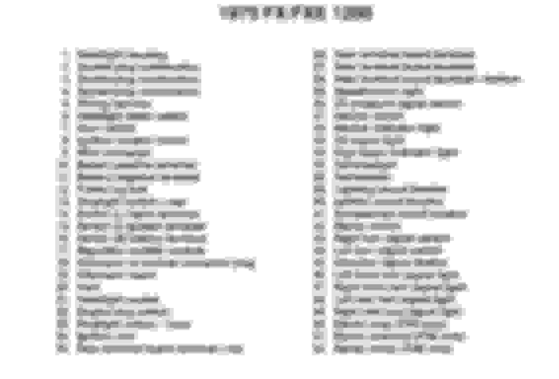
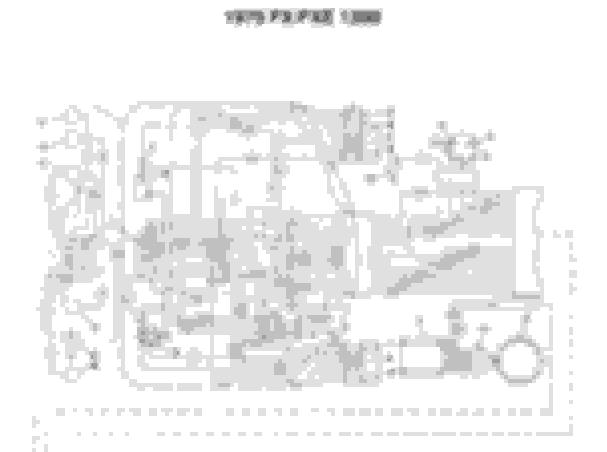
But I did get a chance to look at the 1975 FX/FXE 1200 wiring diagram this evening.
It shows a black and a pink wire leaving the regulator.
Possibly a misprint, but on the second half of the diagram they both show black.
One black wire goes to the positive battery terminal.
The other black wire goes to a connector that shows a pink wire.
The pink wire goes to a wiring harness socket (#4 on the diagram), then terminates at the tachometer.
I can only speculate that the third wire coming out of the sheath may be entering it near the rear exhaust pipe as pictured in the top photo labeled �extra wire�. Tomorrow I may have a chance to slice the sheath off and see if that is the case.
Regardless, that still leaves me with the prospect of being unable to replace the existing regulator, as the wiring diagram would indicate that it in fact drives the tachometer. All the replacements are single wire units.
It seemed like such a simple thing to replace.
1975 FX/FXE 1200 Wiring Diagram Legend
1975 FX/FXE 1200 Wiring Diagram 1
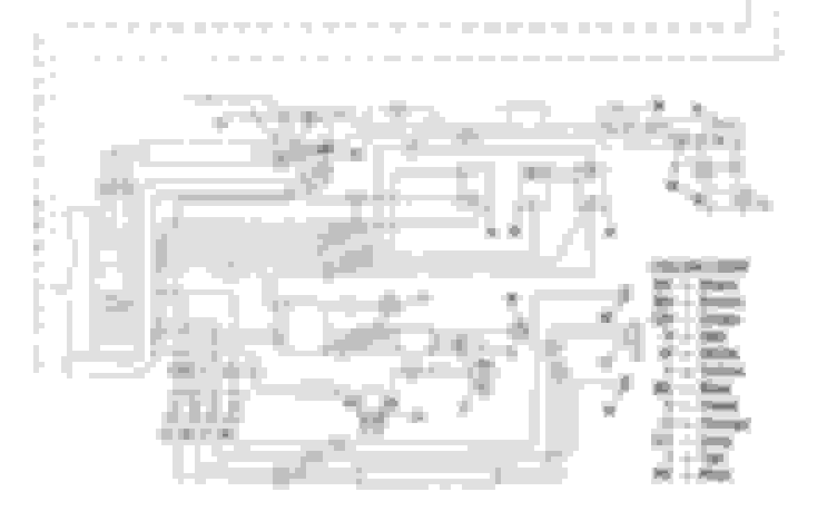
1975 FX/FXE 1200 Wiring Diagram 2
Last edited by Rusty Axle; 06-23-2018 at 08:38 PM.
Where is the electric tach driven from on other models?
It looks like I need to convert to whatever that method is.
That way I can install the high quality Cycle Electric setup and hopefully never have to worry about a voltage regulator ever again.
I'm Tellin ya I have Never seen a Tach Diven by the Regulator... can't even see how it could be done..
Going out to look at a '74 right now....
OK of 2 I can lay my hands on right now.. one is a Known Replacement.. neither have a Pink Wire..
I know there is an OE setup around here... someplace.. because it is Plugged into a Stator, and I have not located it ATT...
At any Rate... Why stress over all that ****???
Run the Tach wire from Trigger Side of coil and be Done... that is how all of Mine work... Except the Mechanical ones of course!!
So all I need to do is run the wire to the trigger side of the coil (#24 in the diagram above) - that would be the side that runs to the points (#8 in the diagram above)?
So all I need to do is run the wire to the trigger side of the coil (#24 in the diagram above) - that would be the side that runs to the points (#8 in the diagram above)?
Edit; Upon Looking into this deeper... I notice that the Part Numbers are Different for the Early FX, as compared to '76 or so and Up...
Tach. Darn it!!!
I would hook up my Tach as Stated to "see" if it is Functional with Coil Triggers applied..
I am Finding hard to Fathom that anyone would measure AC Voltage [or DC for that Matter] to Count RPM's!!!!
But... Wierder things have Happened!!!
And as far as Wiring the Tach....
Yep
That's How Mine is Working!!
I'm sitting here trying to Wrap my head around how in the Wide World Of Sports, the Charging System could operate a Tach?????
BTW I seem to have "misplaced" my Known Stock 4 pin System.. It burrowed into a Hole in my Mess!!!!!
Just as well tho... I disliked it Very Much indeed.. Especially since I Use AGM Batteries now.. Not a "vented" wet cell on the Place!!!
Edit again;
It now occurs to me that it may be Possible to Measure the Frequency of the AC voltage from the Charging System.. and then send Lower Voltage Signal to the Tach....
Maybe??? Still a Dumb way to do things!!!!
Haven't had a chance yet, RacePres. My job has me on the road frequently and this coming week will be away as well. So it may be a few weeks before I have a chance to try it.
Last edited by Rusty Axle; 06-28-2018 at 09:44 AM.

 06-21-2018, 12:29 PM