Ape and Nacelle Install.
#1
 07-16-2012, 11:07 PM

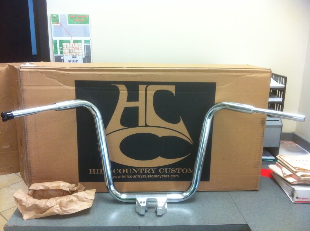
Scattered amongst this forum are bits and pieces of my upcoming project. I decided to combine it all into one thread. I plan on it being a very detailed install of a set of 16" x 1 1/2" Buffalo Apes with chrome controls, chrome switches, chrome switch housings with chrome hardware and chrome levers. All control pieces being genuine HD pieces from New Castle HD. Motion Pro Stainless Braided cables and brake line. The apes, riser, cables, brake line, poly riser bushings and Avon grips came from Hill Country Custom Cycles. The control wiring extension came from Namz. The parts from New Castle will be here tomorrow and I will have everything on hand to begin this little project. I will also be installing the Nacelle that I scored on Ebay a while back for dirt cheap. I plan on this being a very picture heavy thread accompanied by the steps performed and tools used and any mods required to make a part fit. Hopefully the mods will not be upset with all of the pics. If anyone has any comments or questions along the way please feel free to throw them on here. To kick this thread off and for a refresher to some of the members here that have seen the pics and to bring everyone else up to speed, here are some pics of what I have so far.
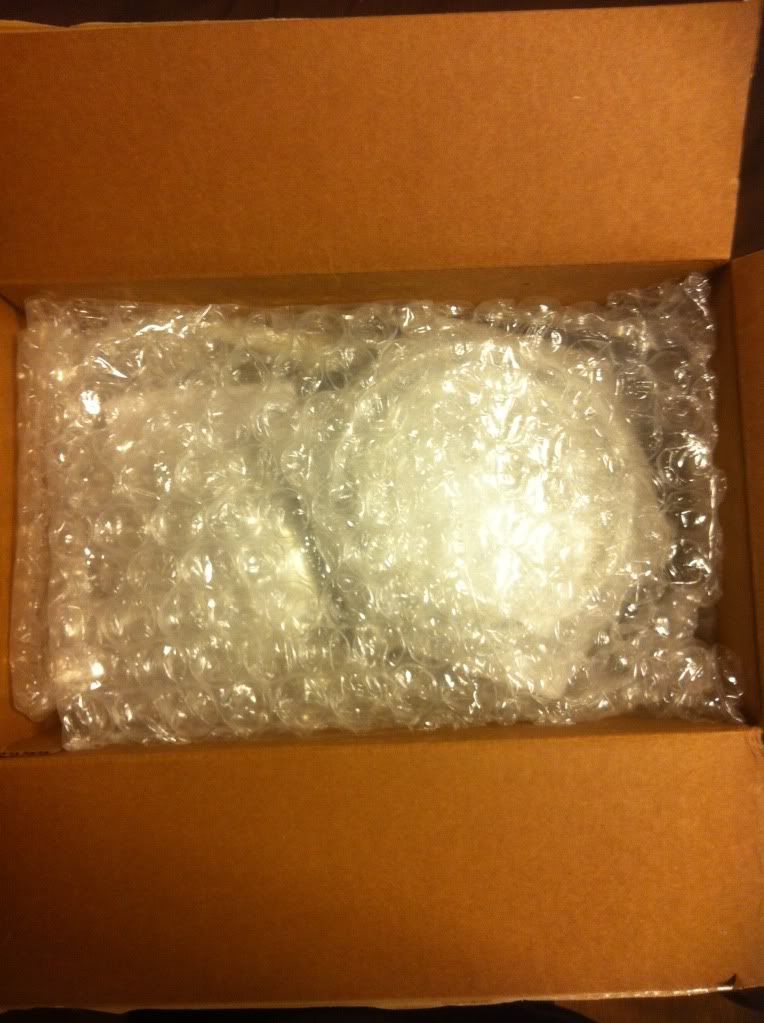
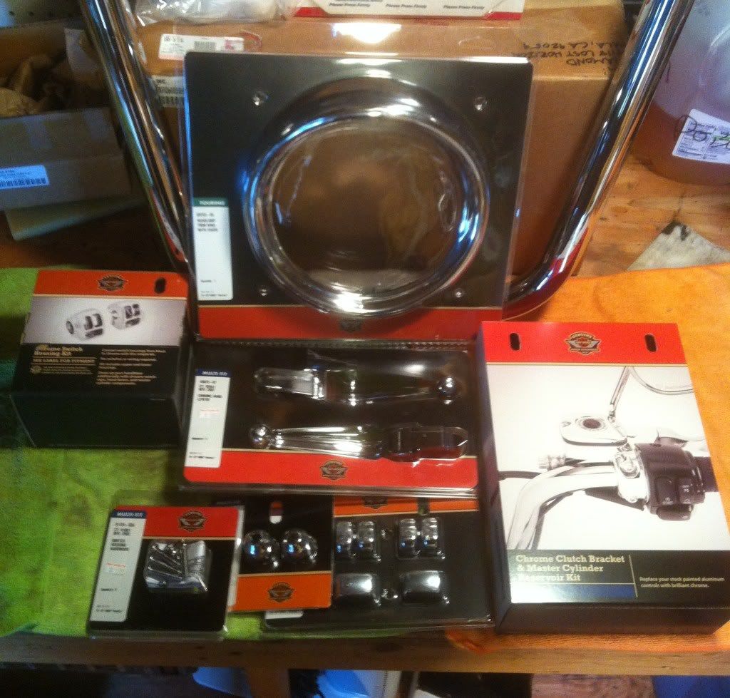
First off is the brand spankin new Nacelle I scored for 200 something dollars. This thing was still in the factory sealed box when it arrived.

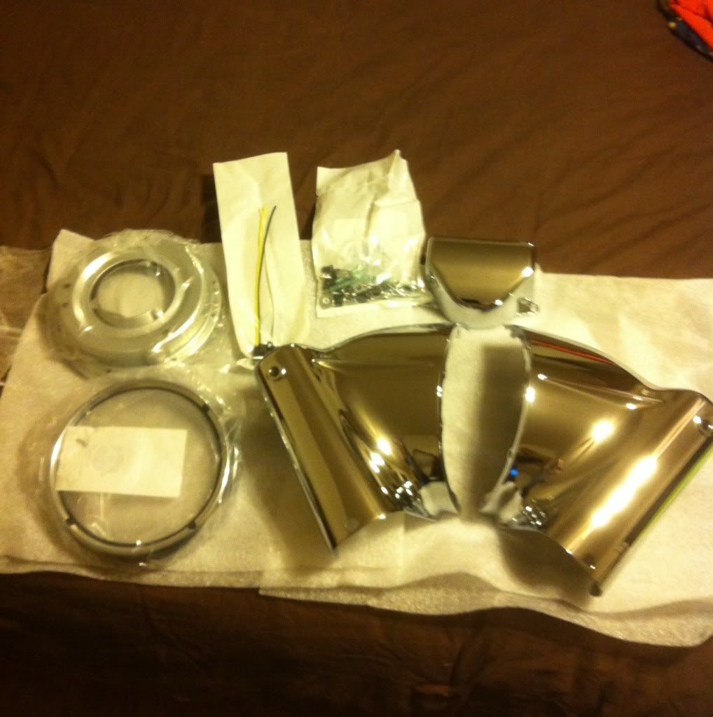
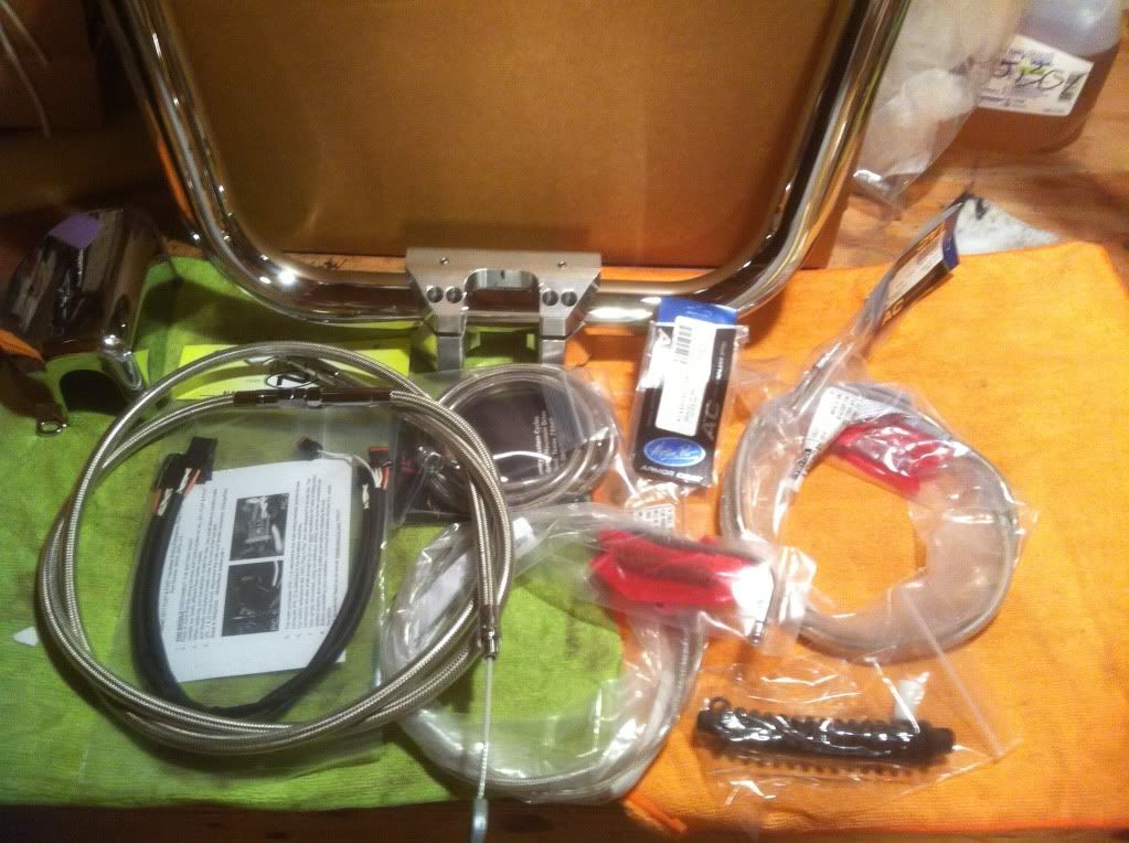
Here are a few pics of the apes and most of the goodies that go along with them. The throttle and idle cables are 39", the clutch is 74" and the brake line is 54". When the parts from New Castle arrive tomorrow I will snap a shot of them.
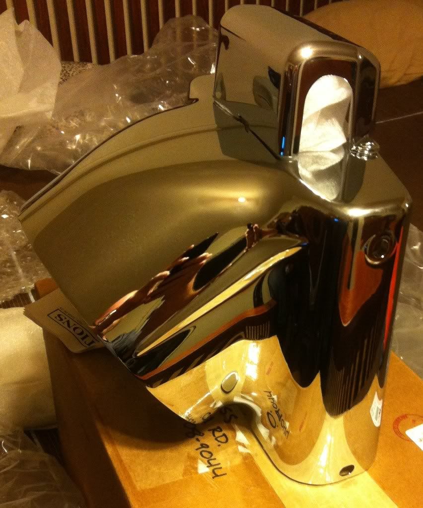
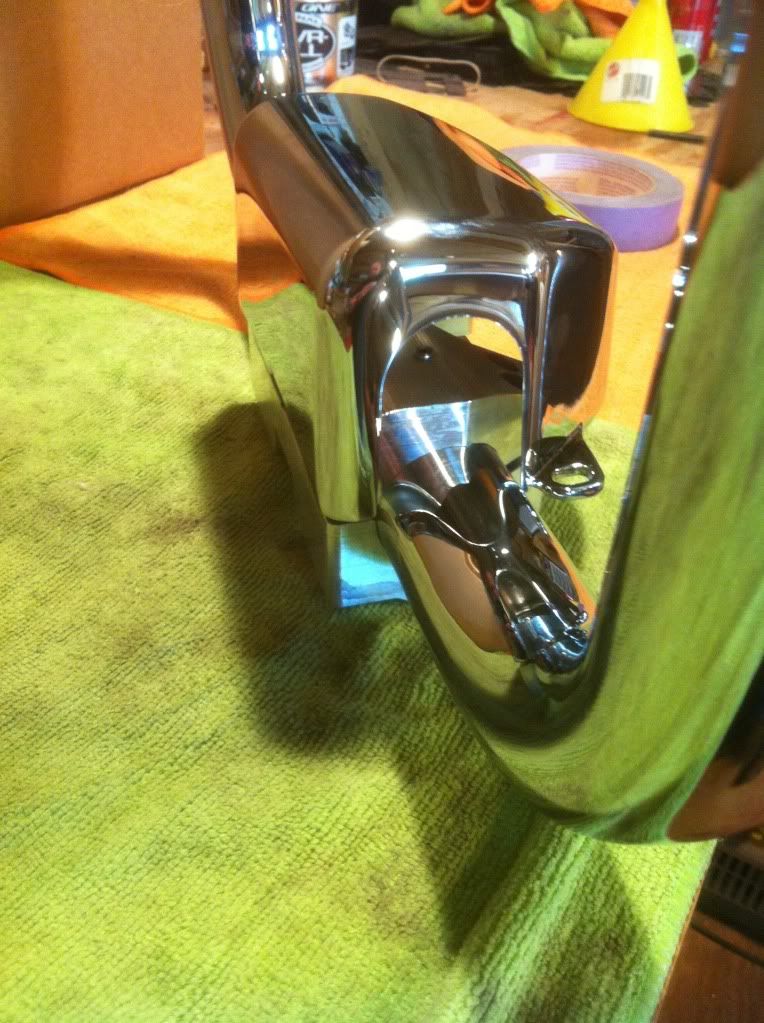
Here you can see that some metal removal is in order to get the Nacelle riser cover to fit the 1 1/2" bars. Just another walk in the park.
First off is the brand spankin new Nacelle I scored for 200 something dollars. This thing was still in the factory sealed box when it arrived.
Here are a few pics of the apes and most of the goodies that go along with them. The throttle and idle cables are 39", the clutch is 74" and the brake line is 54". When the parts from New Castle arrive tomorrow I will snap a shot of them.
Here you can see that some metal removal is in order to get the Nacelle riser cover to fit the 1 1/2" bars. Just another walk in the park.
Last edited by ghostrider69; 07-16-2012 at 11:13 PM.
#3
07-17-2012, 10:04 AM
Road Warrior
Join Date: Jun 2010
Location: OC,NY
Posts: 1,829
Likes: 0
Received 0 Likes
on
0 Posts
Hey Ghost everything is looking great !!! BUT now for the bad news besides the cover not fitting over. Those risers will not work with the Nacelle unless you put some spacers under neath to raise them up. The rise is very short and will not allow you to push the two Nacelle halves together.
I have the same risers (but in the 1.25" version) sitting in a box in my attic. I ran into this problem when installing my Nacelle with my Carlini Gangster full 1.25 Apes. So unless something is different with the 1.50 "risers you will most likely have the same problem. Just wanted to give you the heads up so you are prepared.
I just went with the Harley 1.25 " Beach Bar risers which fit perfect under the cover and all. You do not have that option being you have the 1.50" bars. So spacers or different 1.50 risers like the Carlini Piston or Boob riser will work.But the cover does not fit with these ether. The Carlini High Roller does not work ether with out trimming the Nacelle itself. Hope this helps.
#5
07-17-2012, 05:16 PM
Thanks guys.
Malingerer, it makes perfect sense. A riser made to be used with a Nacelle will not work with a Nacelle. Thanks for the heads up. I will keep an eye out for it. What was causing the Nacelle halves to not come together? Are the 1/4" standoffs machined into the bottom of the riser to large a radius and the Nacelle halves hitting them or are they not tall enough which would warrant the need for additional spacers. On a side note a package arrived today from New Castle HD.
Malingerer, it makes perfect sense. A riser made to be used with a Nacelle will not work with a Nacelle. Thanks for the heads up. I will keep an eye out for it. What was causing the Nacelle halves to not come together? Are the 1/4" standoffs machined into the bottom of the riser to large a radius and the Nacelle halves hitting them or are they not tall enough which would warrant the need for additional spacers. On a side note a package arrived today from New Castle HD.
#6
07-17-2012, 07:17 PM


Thanks guys.
Malingerer, it makes perfect sense. A riser made to be used with a Nacelle will not work with a Nacelle. Thanks for the heads up. I will keep an eye out for it. What was causing the Nacelle halves to not come together? Are the 1/4" standoffs machined into the bottom of the riser to large a radius and the Nacelle halves hitting them or are they not tall enough which would warrant the need for additional spacers. On a side note a package arrived today from New Castle HD.
Malingerer, it makes perfect sense. A riser made to be used with a Nacelle will not work with a Nacelle. Thanks for the heads up. I will keep an eye out for it. What was causing the Nacelle halves to not come together? Are the 1/4" standoffs machined into the bottom of the riser to large a radius and the Nacelle halves hitting them or are they not tall enough which would warrant the need for additional spacers. On a side note a package arrived today from New Castle HD.
#7
07-17-2012, 07:29 PM

Advanced
Join Date: Sep 2011
Location: Dade City, FL
Posts: 57
Likes: 0
Received 0 Likes
on
0 Posts
Trending Topics
#8
07-17-2012, 08:08 PM
Road Warrior
Join Date: Jun 2010
Location: OC,NY
Posts: 1,829
Likes: 0
Received 0 Likes
on
0 Posts
Thanks guys.
Malingerer, it makes perfect sense. A riser made to be used with a Nacelle will not work with a Nacelle. Thanks for the heads up. I will keep an eye out for it. What was causing the Nacelle halves to not come together? Are the 1/4" standoffs machined into the bottom of the riser to large a radius and the Nacelle halves hitting them or are they not tall enough which would warrant the need for additional spacers. On a side note a package arrived today from New Castle HD.
Malingerer, it makes perfect sense. A riser made to be used with a Nacelle will not work with a Nacelle. Thanks for the heads up. I will keep an eye out for it. What was causing the Nacelle halves to not come together? Are the 1/4" standoffs machined into the bottom of the riser to large a radius and the Nacelle halves hitting them or are they not tall enough which would warrant the need for additional spacers. On a side note a package arrived today from New Castle HD.
#9
07-17-2012, 09:36 PM
Thanks everyone.
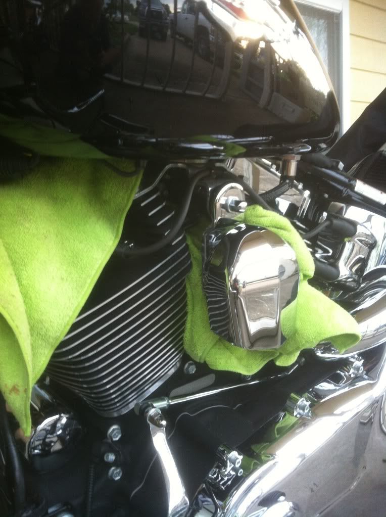
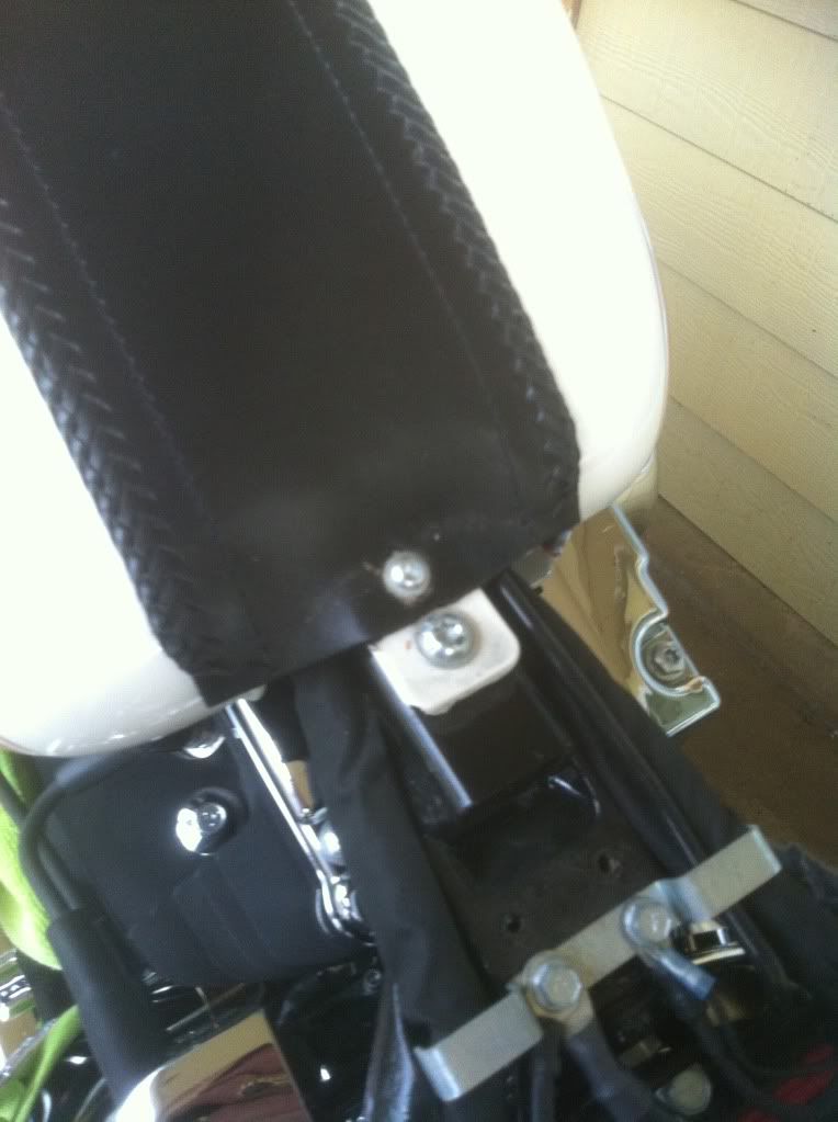
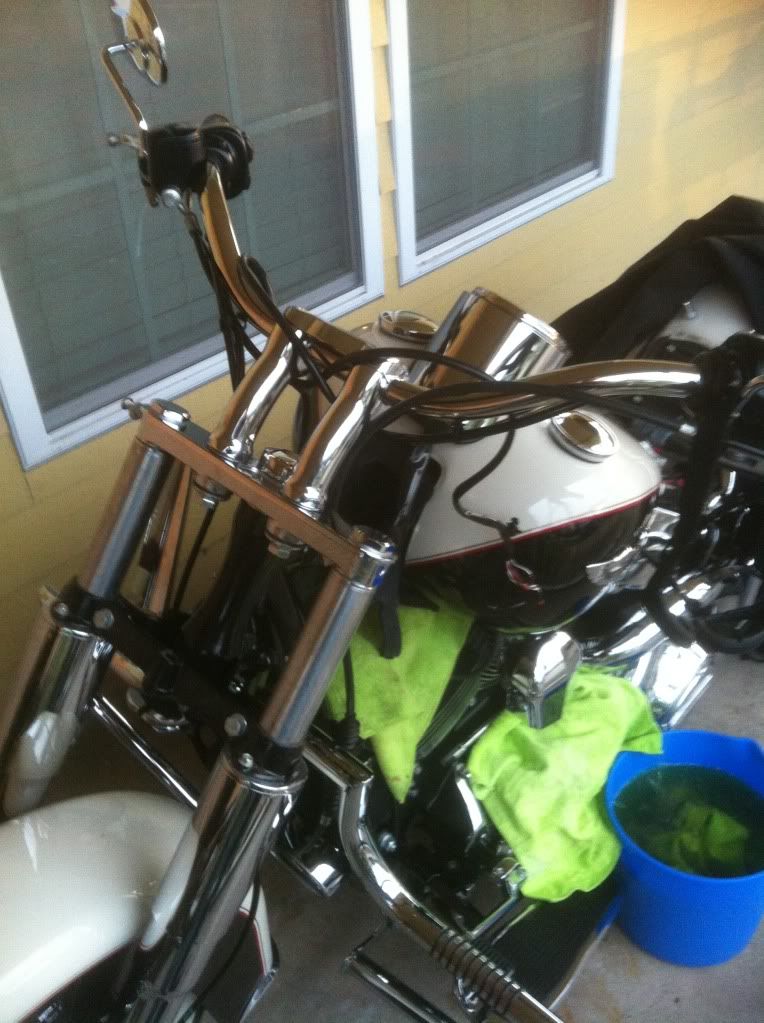
Malingerer, it makes perfect sense. Just by eyeballing everything it doesn't look like it needs but maybe another 1/4" of rise. I'll get around to test fitting the riser and Nacelle and take a few measurements to see how much it needs. If anything I will turn a couple of spacers on my lathe out of solid stock billet aluminum I have laying around. I had a little time to spare this evening so I decided to kick this project off. I first removed the seat. I decided that it would be easier to just slide the tank back to get to all of the plugs versus completely removing it. So, first I stuffed a few thick, used microfiber rags between the jugs and heads to catch any gasoline that would leak from the quick disconnect when I pulled it off. To unhook the quick disconnect fuel line from the injector rail I prefer to just use to long, skinny flat head screw drivers to push in on each side of the clip and then push the clip up with them. Once the clip was completely released I easily pulled the fuel line off of the fuel rail. After starting this project I realized that my three 5 gallon gas cans were full of 87 octane to I could not use one of them to can the 93 octane that was in the tank. So, I improvised with a wash bucket. I then proceeded to unbolt the tank. The rear Torx head bolt is a T40 and the front mount bolt is a 14mm. I then slid the tank back a couple of inches so that I could get to the clips that hold the rubber boot in place that is under the tank, carefully watching the wires and vent line. After I removed the metal clips I was able to slide the tank back to gain access to the electrical connectors for the lights and controls and unplug them. I then removed the locknut from the marker light toggle switch that is on left rear side of the fork tins and unplug it. Using a 9/16" socket I unbolted the headlight and removed it. With an allen wrench, the size I don't remember, I unbolted the light bar and removed it. Then used a T27 Torx to remove the mounting bolts from the rear tin covers and to get them out of the way. No wires need be cut during the removal. That is all I had time for today. Tomorrow I will unhook the cables so that I can remove the bars then we will start going back together with it. As before if anyone has any comments or questions please feel free to post them. Here are a few pics of the progress.
Malingerer, it makes perfect sense. Just by eyeballing everything it doesn't look like it needs but maybe another 1/4" of rise. I'll get around to test fitting the riser and Nacelle and take a few measurements to see how much it needs. If anything I will turn a couple of spacers on my lathe out of solid stock billet aluminum I have laying around. I had a little time to spare this evening so I decided to kick this project off. I first removed the seat. I decided that it would be easier to just slide the tank back to get to all of the plugs versus completely removing it. So, first I stuffed a few thick, used microfiber rags between the jugs and heads to catch any gasoline that would leak from the quick disconnect when I pulled it off. To unhook the quick disconnect fuel line from the injector rail I prefer to just use to long, skinny flat head screw drivers to push in on each side of the clip and then push the clip up with them. Once the clip was completely released I easily pulled the fuel line off of the fuel rail. After starting this project I realized that my three 5 gallon gas cans were full of 87 octane to I could not use one of them to can the 93 octane that was in the tank. So, I improvised with a wash bucket. I then proceeded to unbolt the tank. The rear Torx head bolt is a T40 and the front mount bolt is a 14mm. I then slid the tank back a couple of inches so that I could get to the clips that hold the rubber boot in place that is under the tank, carefully watching the wires and vent line. After I removed the metal clips I was able to slide the tank back to gain access to the electrical connectors for the lights and controls and unplug them. I then removed the locknut from the marker light toggle switch that is on left rear side of the fork tins and unplug it. Using a 9/16" socket I unbolted the headlight and removed it. With an allen wrench, the size I don't remember, I unbolted the light bar and removed it. Then used a T27 Torx to remove the mounting bolts from the rear tin covers and to get them out of the way. No wires need be cut during the removal. That is all I had time for today. Tomorrow I will unhook the cables so that I can remove the bars then we will start going back together with it. As before if anyone has any comments or questions please feel free to post them. Here are a few pics of the progress.