Harley Davidson Touring: How to Remove Inner Fairings
Removing your inner fairing for paint or to upgrade the stereo isn't that hard. It's also a necessary step if you want to get to your forks for maintenance or upgrades. Follow along while we show you how.
This article applies to the Harley Touring Models (2000-2013).
Removing the inner fairing of the Harley Davidson batwing style fairing is not hard. Follow along as we remove it from a 2008 Street Glide; other models are similar going back many years. If you don't have one, the factory shop manual is a great reference to have handy.
Materials Needed
- Snap ring pliers
- T-27 Torx wrench (use the long one with a T-handle..it's easier)
- T-25 Torx wrench
- 3/16" Allen wrench (long one with T-handle)
- 5/16" socket and ratchet handle
- 7/8" open end wrench
- 9/16" open end wrench
- 1/2" open end wrench
- Phillips screwdriver
- Flat head screwdriver
Step 1 – Remove outer fairing
- Remove the left saddlebag and side cover, then pull out Maxi Fuse.
- Remove three T-27 screws from front fairing and pull out windshield. Put the middle screw back in place loosely. This will keep your outer fairing from falling on your fender when you remove the four inner screws (next step) and preventing damage to either the fairing or fender. (Figure 1)
- Remove two T-27 screws from each side of inner fairing (one silver and one black each side). (Figure 2)
- While supporting outer fairing, remove middle windshield screw from step 2. Pull outer fairing forward and disconnect headlight wiring. Set outer fairing aside.
- Take a lot of pictures to help you remember exactly how wires are run when you reassemble. (Figures 3 and 4)
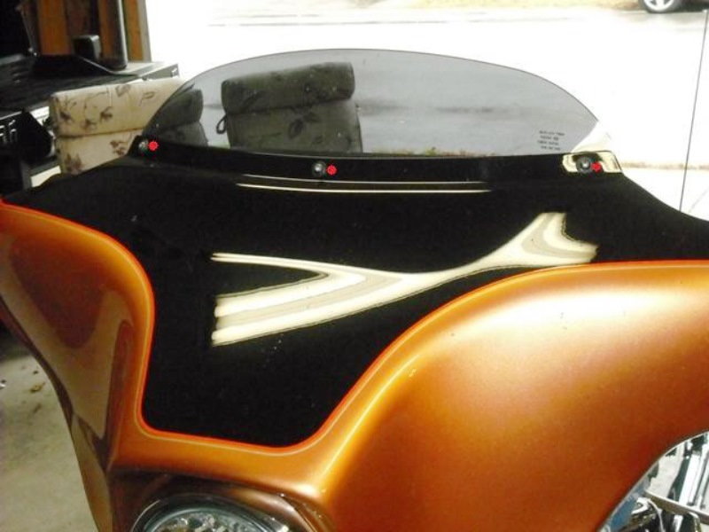
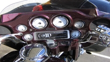
Figure 1. The classic Harley batwing fairing. 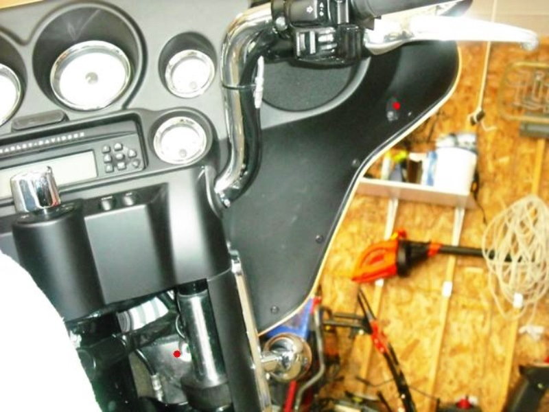
Figure 2. Red dots indicate the outer fairing screws. 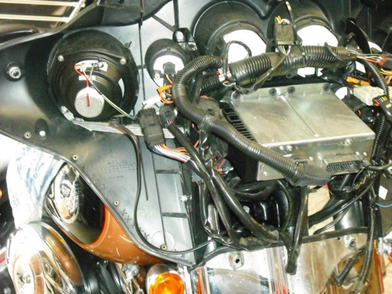
Figure 3. Taking pictures will help with reassembly. 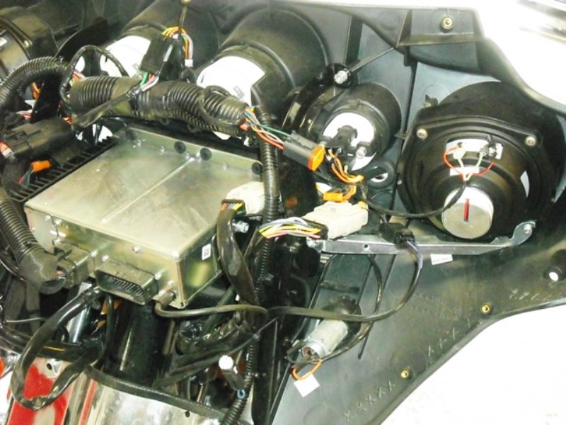
Figure 4. There is a maze of wiring inside.
Pro Tip
Mark every wire you disconnect with masking tape, so you know where it plugs back in.
Step 2 – Disconnect wiring, lights and switches
- Disconnect left and right front turn signal/aux lamp connectors. (Figure 5)
- Remove the four connectors from the fairing support bracket (silver), they just slide right off. (Figure 6)
- Remove the two bolts from each of the support brackets (silver). The inside ones are 3/16" Allen bolts and the outside ones are T-25 Torx. (Figure 7)
-
Turn forks to the left and put key in ignition lock. Take a small screwdriver, and under the ignition you will find a little button. Push up the button and turn the key to the left a little bit. That will release everything. Pull ignition out. Note Figure 8.
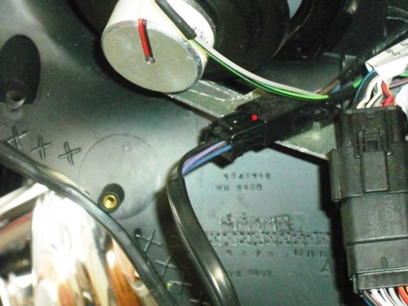
Figure 5. Unplug this connector (red dot). 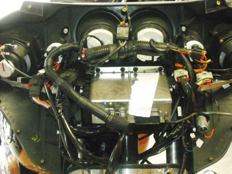
Figure 6. Remove these connectors from the bracket. 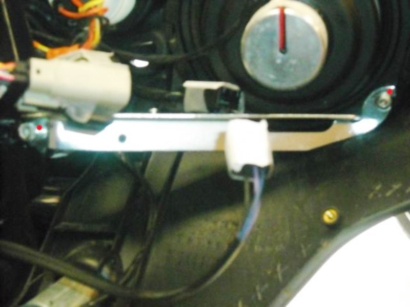
Figure 7. Unscrew the support brackets. 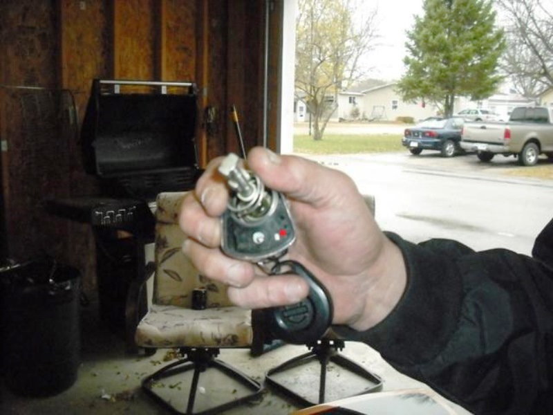
Figure 8. The button you are going to push is located at the red dot. - Unscrew collar with 7/8' open end wrench. Remove nut, collar and black spacer. Remove the switch position plate. (Figure 9) Note: If the forks should get locked, take a regular screwdriver and put it down the hole where the switch was into the notch. Turn it to the right and the forks unlock.
- Remove the two T-25 Torx screws—one each side—with washer. Turn forks left and disconnect the switch connector. You can then remove the cap. It may be easier to remove the rubber grommets (located on the side) first. (Figures 10 and 11)
- Remove two screws from turn signal. Make a note on how the wire runs for the turn signal. Remove signal and front chrome skirt. (Figure 12)
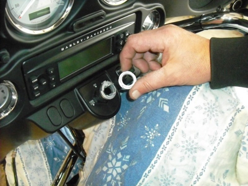
Figure 9. Unscrew switch plate. 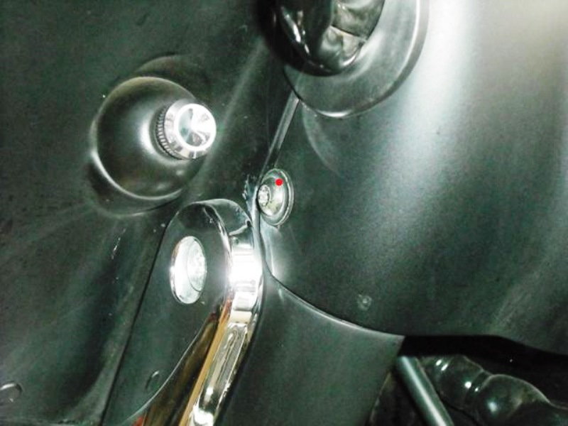
Figure 10. Disconnect switch connector. 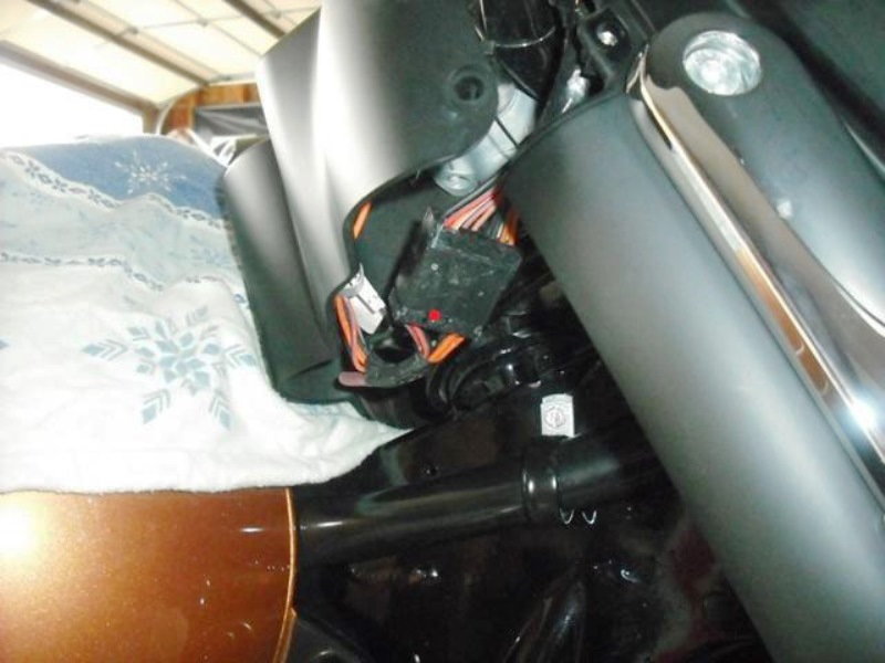
Figure 11. Ignition key switch wiring now accessible. 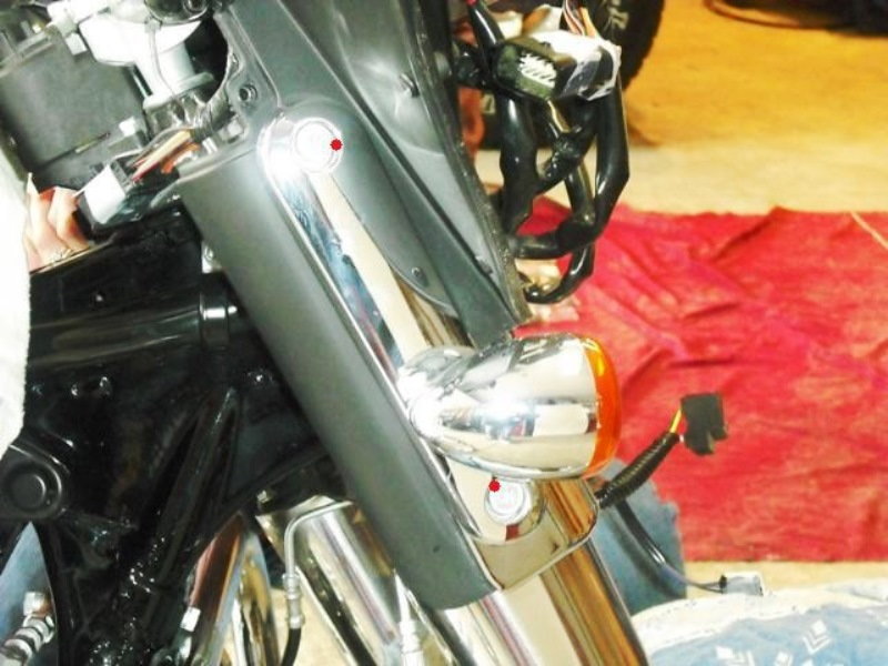
Figure 12. Remove the turn signals.
Step 3 – Remove clutch cable
- Slide rubber boot up adjustment cable. Using 9/16" and 1/2" wrenches, break locking nut free. Screw adjusting piece in to make slack in the clutch lever. (Figure 13)
- Remove snap ring from the pivot pin of the clutch lever and pull pin out. (Figure 14)
- Remove two T-27 Torx screws with washers from clutch bracket.
- Remove clutch lever from bracket and pull anchor pin from cable. (Figure 15)
- Pull the clutch cable through the inner fairing to the front, just enough so it clears the fairing.
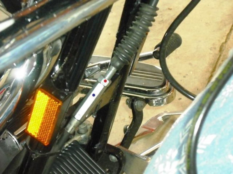
Figure 13. Clutch cable adjustment. 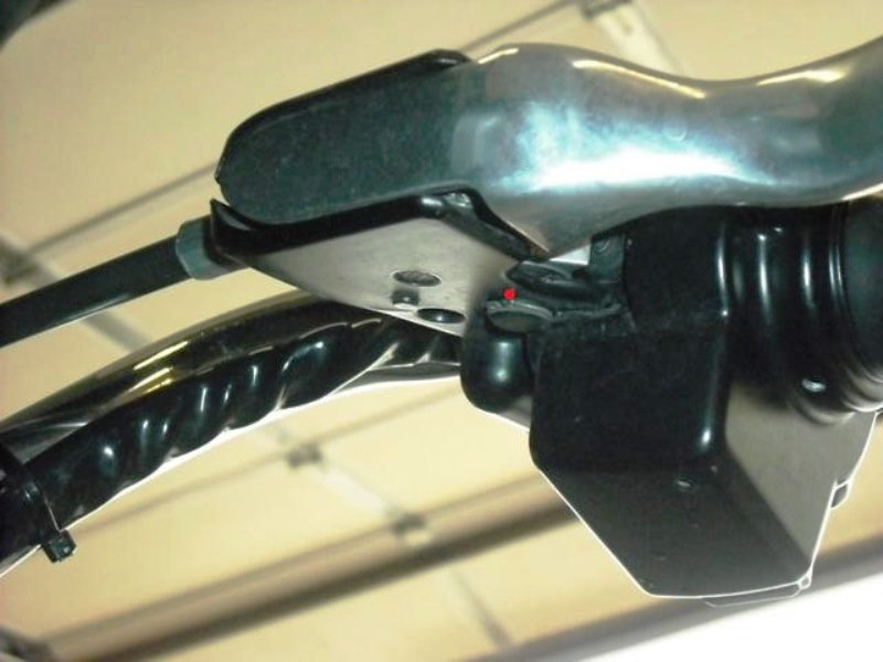
Figure 14. Clutch pivot pin. 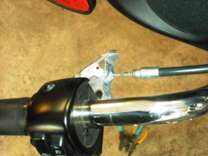
Figure 15. Remove clutch cable.
Step 4 – Remove lighter, speakers and gauges
- Disconnect two wires from cigarette lighter. Put your finger in the cigarette socket. Unscrew the outer cover of the cigarette lighter. Your finger is in the cigarette socket to keep it from turning so you can unscrew the back cover. (Figure 16)
- Disconnect wires from speakers. Remove remaining two screws from speaker to remove speaker. Note: These two screws have to go back on the top of the speaker. The third screw was removed earlier when you took out the silver bracket. (Figure 17)
- Unscrew the rubber boot from the reset switch and pull switch from hole.
- Unplug speedo and tach. Remove the black plastic brackets from the speedo and tach. You will see that the bundle of wire is clipped to the bracket of the speedo. Do NOT disconnect the bundle from the bracket. Remove speedo and tach. They push out towards the back of the bike. (Figure 18)
- Unplug the rest of your gauges. Do NOT remove them at this time. You can do that when you move the inner fairing to the bench.
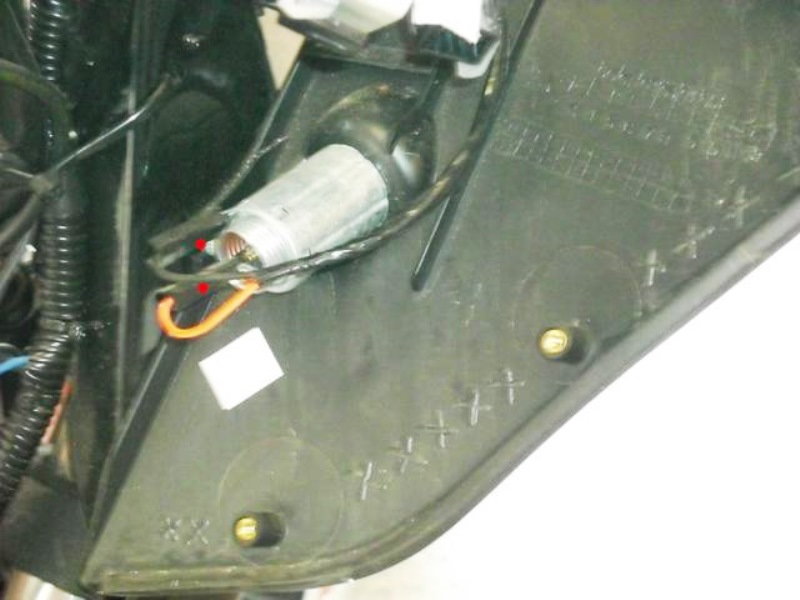
Figure 16. Cigarette lighter outlet. 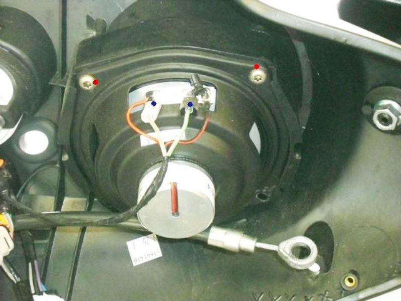
Figure 17. Front stereo speaker. 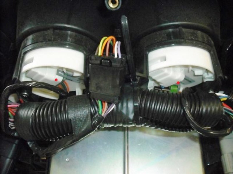
Figure 18. Speedo and tachometer gauges.
Step 5 – Remove inner fairing
- Pull the bottom part of fairing and the black bracket away from the short dowel pin they are on (both sides). Just pull them out and up a little bit so they clear the pin.
- Raise the fairing and black bracket together a little bit. Grab the black bracket (that you just released from the dowel pin) as well as the fairing and separate them. Pull the bracket toward the front of the bike and the fairing towards the rear of the bike. Radio is in tight, but it will come free of the fairing. Just wiggle it some.
- Once the radio clears the inner fairing, you can then pull the inner fairing up and back (towards the back of the bike). Inner fairing is now removed. Take it to the bench. If it gets hung up, just go slow and see where the problem is. (Figure 19)
- Put bolts back in black bracket, loosely. This will hold the radio in place.
- Remove the 5/16" bolts for the gauges. The gauges will then push out through the front. (Figure 20)
- Remove nuts from back of mirrors. Pull mirrors free. Note: The black pieces under the nut are marked with an L and an R. Put them back on the correct sides when you reassemble. Remove rubber grommet.
- Remove the two T-25 Torx screws from the switch holders. Don’t try to pry the switches out of the holder, it’s easier to just take the screws out. (Figure 21)
- Success! (Figure 22)
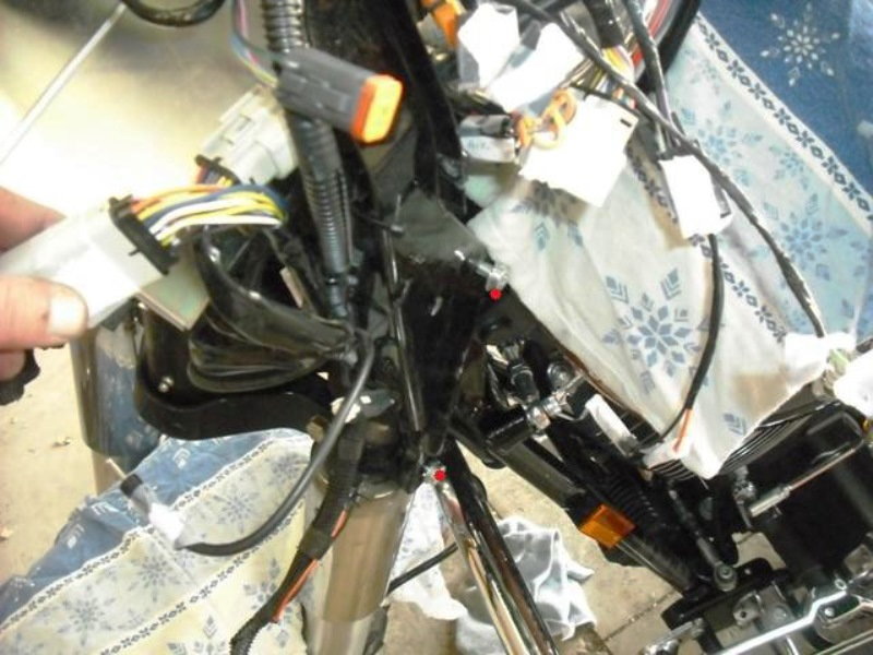
Figure 19. Wiggle the radio out. 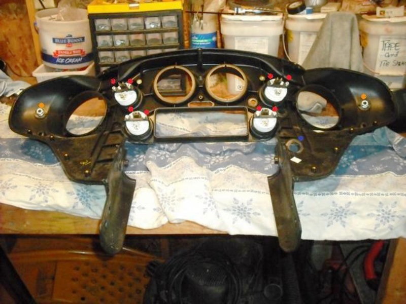
Figure 20. Remove auxiliary gauges. 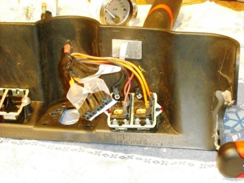
Figure 21. Electrical switch holder. 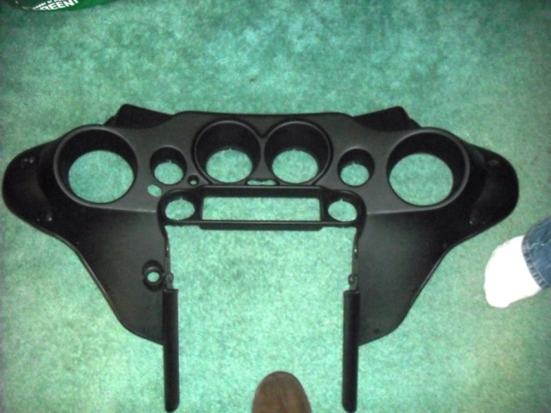
Figure 22. Finally, the bare inner fairing ready for customization.
Step 6 – Reassembly
Reassembly is in reverse of above. Your shop manual will provide proper bolt torques and clutch adjustment procedure.
Related Video: Fairing Removal
Related Discussion
- Step by Step Inner Fairing Removal - HDForums.com