HD Harness wire color question
#1
 01-03-2013, 08:32 AM

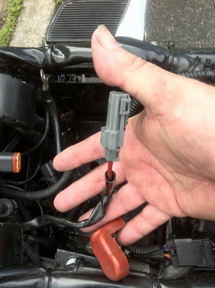
I am trying to install a new Dakota MCV 7000 series Gauge on my 2000 Dyna FXDX. Have bought plug to put into stock HD Harness. Started identifying wires from MC7000 versus HD Harness. Have Identified all of them except ONE that I cannot find the use for. On the plug there is this ORANGE wire that SEEMS to be a common ground on the other side (one going to the speedometer) because it turns to black on the other side of plug. Does anyone know what this ORANGE WIRE IS. Pic of main harness joined. Have also included wiring color code from DAKOTA. On this wiring code I also do not see the ORANGE on the HD HARNESS. AND LASTLY on the MCV 7000 there is a WHITE/RED wire that IS NOT LINKED to HD Harness. This white/red is supposed to be "Constant fused +12 V Battery Power". No such thing on HD HARNESS, do I have to pass a separate wire directly to battery.
Thanks for the information and help because I am puzzled here!
Thanks for the information and help because I am puzzled here!
#2
01-03-2013, 09:44 AM

Join Date: Feb 2007
Location: Harmelen (The Netherlands, Europe)
Posts: 8,986
Received 867 Likes
on
576 Posts
Here are the color codes for your 2000 Model Dyna 12 points Deutsch Connector:
pin 1 Orange/White (12 v ignition switch controled acc power)
pin 2 White/Green (speedo signal out)
pin 3 Brown (12 v power to right turn indicator)
pin 4 White (12 v power to high beam indicator)
pin 5 Violet (12 v power to left turn indicator)
pin 6 Orange (12 v ignition switch controled instruments power)
pin 7 Pink (tach signal)
pin 8 Tan (12 v power to neutral indicator light)
pin 9 Green/Yellow (12 v power to oil indicator light)
pin 10 Black/Yellow (12 v power to check engine control light)
pin 11 Black (ground for control lights)
pin 12 Black (ground for speedo & tacho)
What MCV7000 are you trying to install:: 4, 8 or 3 wire?
#3
01-03-2013, 11:37 AM
Thank you very much. This has helped me allot. I will be installing all plugs... Rhee 3 4 and 8. Will be using all of then... I see why Dakota doesn't use the orange, because you have this on the white red which is orange white on hd harness. Will Tryto check ohm sender values to see if I can plug it to new gauge also. Only thing is will probably have to pass new write for constant fused 12 volts for gauge clock because none fir old Mickey mouse hd gauges... If I am wrong correct me please and once again thanks for the orange wire...
#5
01-03-2013, 05:29 PM
Just checked and it doesn't have this plug under the seat but the getting the twelve volt from RED on Battery is no problem. Now I have another problem. Simple but can't find the answer. Maybe you can help once again.
Would like to know if the FUEL LEVEL SENDING UNIT runs on 240-33 ohms or on 73-10 ohms. OR what is the range in OHMS of the sending unit because on this particula GAUGE (Dakota) I can input the range myself if need be. Not that it is absolutely necessary because I have the gauge on the tank but while I have it on the new gauge might as well put it on.
Thanks again, will post pic of finished gauge when done!!
#7
01-04-2013, 07:14 AM
Trending Topics
#8
01-04-2013, 07:36 AM
Join Date: Feb 2007
Location: Harmelen (The Netherlands, Europe)
Posts: 8,986
Received 867 Likes
on
576 Posts
My pleasure; good luck on this project.
Good idea to post some step by step images!
Edit:
Not sure if you already have this instruction sheet:
http://www.dakotadigital.com/pdf/MCV-7000.pdf
Good idea to post some step by step images!
Edit:
Not sure if you already have this instruction sheet:
http://www.dakotadigital.com/pdf/MCV-7000.pdf
Last edited by FXD2003Rider; 01-04-2013 at 07:43 AM.
#9
01-14-2013, 05:24 PM
Finally done and result is great, took some time to do it right but here is what it looks like and the steps.
Sorry for the pics first time doing a pic as I go thing, hopefully it will help others who go down this path.
Picture 1. Is the original Plug, identified wires and went out to buy DEUTCH Plug from dealer with pins.

Picture 2. Wires from Dakota Gauge in matching position for Harley Harness, wires passed through plug ready for solder to pins

Picture 3. Put cover over wires and placed plugs for new Gauge

Picture 4. Plug wires in Gauge

Sorry for the pics first time doing a pic as I go thing, hopefully it will help others who go down this path.
Picture 1. Is the original Plug, identified wires and went out to buy DEUTCH Plug from dealer with pins.
Picture 2. Wires from Dakota Gauge in matching position for Harley Harness, wires passed through plug ready for solder to pins
Picture 3. Put cover over wires and placed plugs for new Gauge
Picture 4. Plug wires in Gauge
Last edited by FXD2003Rider; 01-15-2013 at 04:17 AM.
#10
01-14-2013, 05:32 PM
More steps
Picture 1: Decided to add BLUE LEDS while I was under the hood

Picture 2: Put machined bracket to stock Handles in order to fit the new Gauge without modifying the Originale parts in any way to bring to bike back to ORIGINAL without hastle if. That is the reason why I made a new PLUG (DEUSCH) for easy replacement of guage if I ever want to put back the original one!

Picture 3: Speed sensor installation for NEW SENSOR for Dakota Gauge, fits in the orignal without problems

Picture 4: Bring 12 VOLT constant from + on battery to supply gauge with constant voltage for the clock and settings

Picture 5: Tywrap wiring on left and right side snug and secure

Picture 1: Decided to add BLUE LEDS while I was under the hood
Picture 2: Put machined bracket to stock Handles in order to fit the new Gauge without modifying the Originale parts in any way to bring to bike back to ORIGINAL without hastle if. That is the reason why I made a new PLUG (DEUSCH) for easy replacement of guage if I ever want to put back the original one!
Picture 3: Speed sensor installation for NEW SENSOR for Dakota Gauge, fits in the orignal without problems
Picture 4: Bring 12 VOLT constant from + on battery to supply gauge with constant voltage for the clock and settings
Picture 5: Tywrap wiring on left and right side snug and secure
Last edited by FXD2003Rider; 01-15-2013 at 04:20 AM.