Alloy Art strut lights & docking points installed on 07 Dyna W/Stupid 180/55-18 Tire
#1
 05-28-2014, 07:54 PM

Alloy Art strut lights & docking points installed on 07 Dyna W/Stupid 180/55-18 Tire
Will add pics as soon as photobucket stops craping out!
Tools Needed for this job:
Wire cutters
wire stripers
terminal crimper
Heat gun (not wife's blow dryer won't get hot enough to shrink DR25)
Small flat blade screw driver
phillips head screw driver
socket wrench
Inch pound torque wrench (not pictured)
7/32 allen wrench
7/32 allen socket
5/64 allen wrench
1/2" socket
T45 socket
3/8-16 thread chasers (not a cutting taps)
Mud Amp conncetor pick tool
straw from wd-40 can
scissors
X acto knife
China marker
Sharpie
Dielectric grease
Blue painters tape
Loctite 243
Small zip ties
[IMG]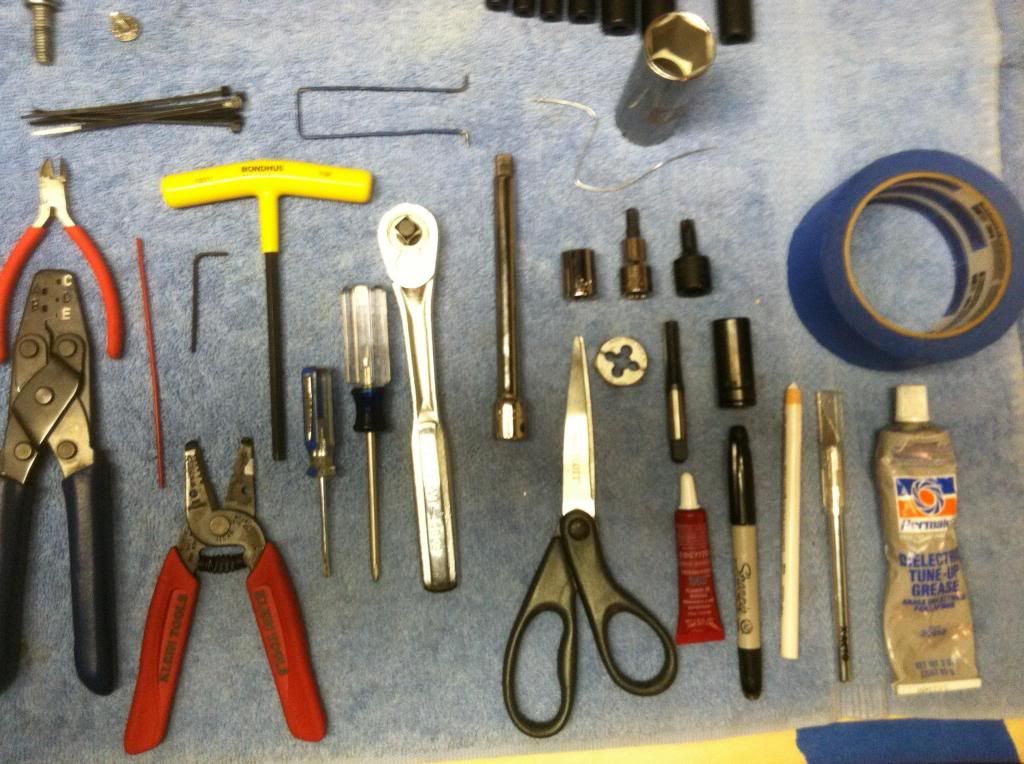 [/IMG]
Start by removing the rear wheel
The shop manual said to disconnect the negative battery terminal I didn't but that is up to you.
Next remove the tail light assembly from its base, disconnect the tail light connector and set it off to the side.
[IMG]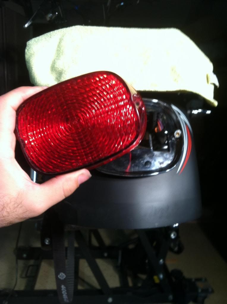 [/IMG]
Now disconnect the turn signal wiring (2 place amp connector) using a small flat blade screw driver depress the tab on the connector and gently pull it free.
[IMG]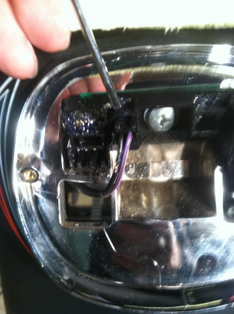 [/IMG]
Once the wiring disconnected remove the turn signal housing and stand off by removing the bolts with a 1/2" socket these can be wrapped in soft cloth, put on Ebay or thrown in the trash as they will not be used for this install.
[IMG]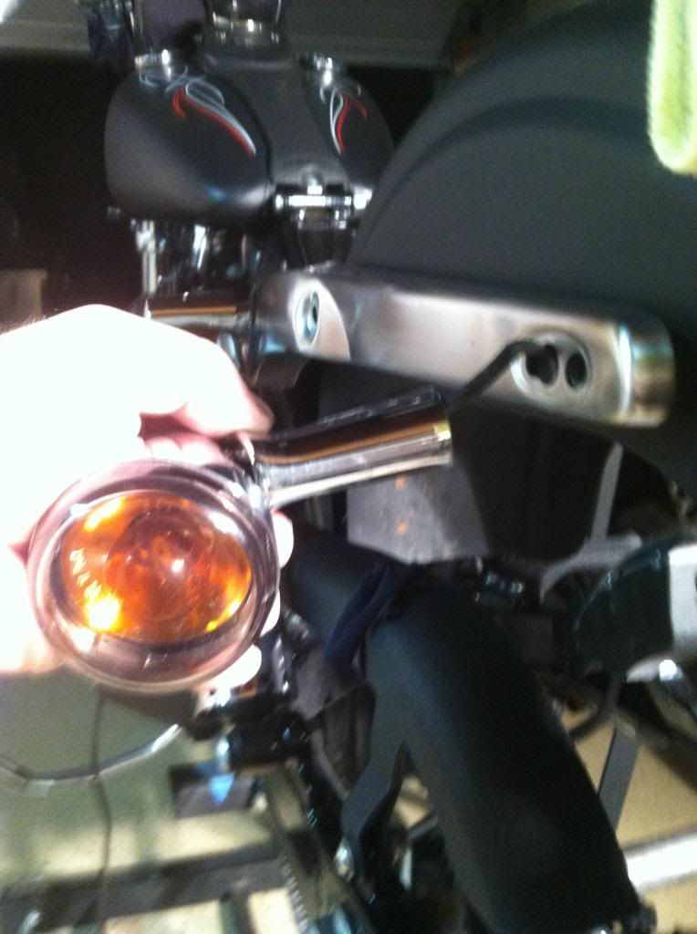 [/IMG]
Now that the turn signals have been removed you will want to only work on one side at a time.
my shop lights were already set up on the left side of the bike so thats where I started
begin by loosening the torx 45 bolt on the strut cover be sure to keep the fender bracket from falling by holding it as remove the bolt or using some blue tape to keep it in place.
[IMG]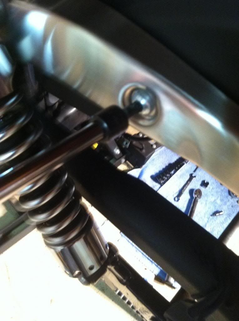 [/IMG]
With the torx bolt removed carefully remove the fender bracket and chuck it in the same place the turn signals wound up.
[IMG]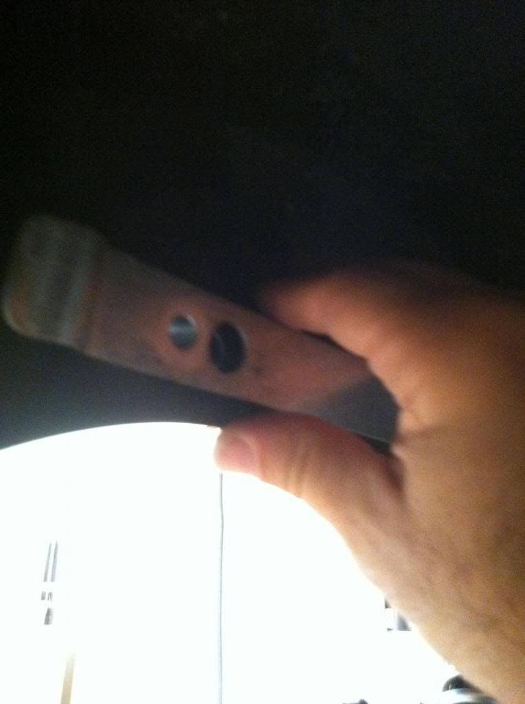 [/IMG]
Next replace the stock fender bracket with the one from your docking hardware or saddlebag kit.
If your are not going to run bags or detachable accessories, you need to buy or a make fender brackets with 3/8-16 threads.
I didn't like any of the harley offerings so I took the brackets from the wide tire kit (PN: 59514-06) to a local fabricator (47 Industries in Raritan, NJ) and had some 3/8-16 top hat bungs welded in place.
[IMG]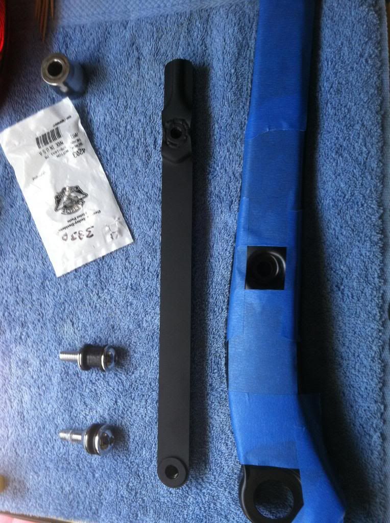 [/IMG]
Install the front most docking point with tapered side facing in or torx bolt (if you're not installing the docking stuff) into the new fender bracket. These will only need to be hand tight for right now.
[IMG]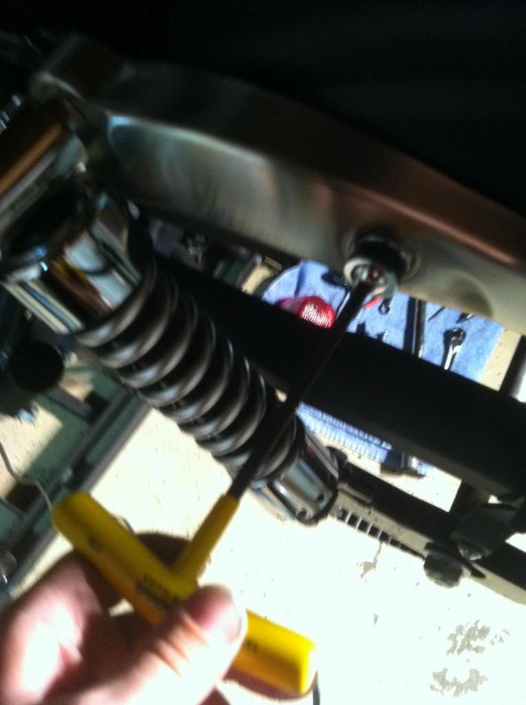 [/IMG]
Before you send the strut lights out to the powder coater or rattle can them in your shed,
you will want to remove the LEDs and do a test fit.
This can be done by removing the set screws that hold them in place with an 5/64 allen wrench. It's much easier to see how to run the wires and how much clearance you have, If the LEDs and wires are out of the way.
[IMG]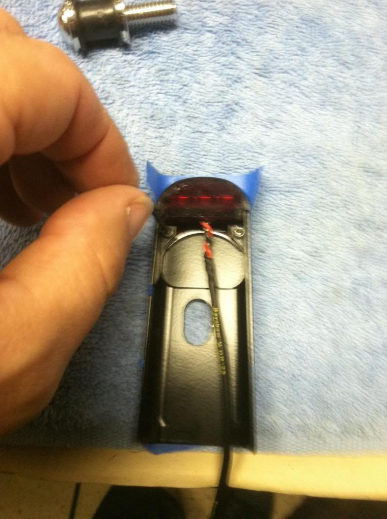 [/IMG]
As a side note these housings look almost identical, have no markings to differentiate the left from from the right and are real easy to get mixed up. Mine also didn't fit worth a damn. So i had to brake out the old dremel and take off some material to make these slide on a little smoother.
Now that the LEDs have been removed: Place the strut light housing over the strut cover do not press it on at this time, just hold it in place and with a free hand slide one of your 3/8-16" bolts through the slot in the housing and give it a few turns with your fingers so that the hosing is now held in place but away from the strut.
At this time you will want to pull the strut light housing toward the rear of the bike so that the slot is pressed against the bolt.
begin to slowly turn the bolt with your socket wrench in the same fashion you would use to close a bench vice this should be a smooth motion.
Note: If the bolt starts to bind or go in crooked as you tighten it. Stop you're installing the wrong one! remove it, set it aside and try the other one.
The correct housing should press it self over the strut cover as you slowly tighten the bolt, explained
in the steps above.
Now that you know your left from right and you're satisfied with fitment, remove the housing and label the inside so they read LH and RH with an engraving tool. (This will make your life easier during final assembly)
If you are running these back to the tail light like the stock ones apply 19" or 20" of DR-25 heat shrink to the wiring. With your heat gun shrink all but the last 2" or 3" i learned the hard way that the heat gun will fuse the wire insulators and the mil spec heat shrink to each other making it damn near impossible to cut and strip back if its too long.
better method would be to run the wires without the heat shrink cut them to length, remove them then add the heat shrink .
The reason I chose Raychem DR-25 over run of the mill heat shrink or even the PVC verity is it's flexibility and resistance to chemicals and abrasion. these wires have to make a few tight turns on this install so I didn't want anything that would kink or bunch up when running it between the strut and the fender. Additionally i wanted to beef up the little @ss 20 gauge wires for my own peace of mind.
Now that you have the wires cut to length and Applied heat shrink to them, reinstall the LEDs back into the strut light housing, it's time to start routing your wires. I took a tip from forum member FenceSC who was nice enough to take one of his apart to show me how he ran his wires.
Take some blue tape and wrap the bare end of the wire so you don't muck up the ends as you run them through the struts.
Starting from the bottom of the strut thread the wire between it and the fender just forward of the bolt so that the wire forms lose happy face (4-6" loop) next you will loop the wire
down and through the hole in the fender that was formerly used by the stock wiring.
[IMG]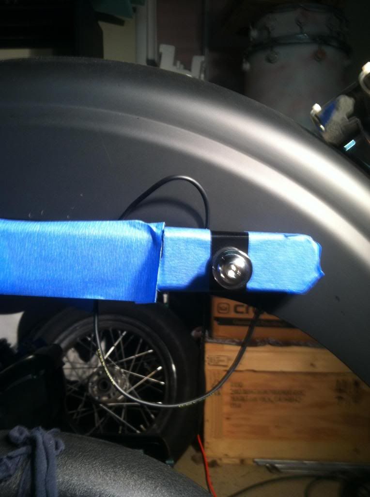 [/IMG]
Now that you have everything routed loosely begin neatening things by pulling the wire from inside the fender as you slowly feed wire from the other side.
[IMG]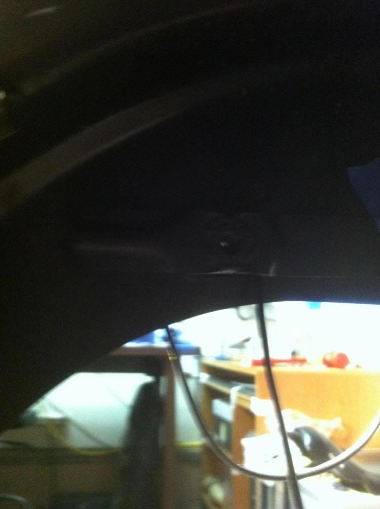 [/IMG]
keep pulling the wire till you're left with a loop small enough to hide behind the strut and the alloy art light housing. carefully begin to tighten the 3/8-16 bolt being sure not to pinch the wire between the housing and the fender.
I used the straw from a WD-40 can to push the wires in place before the last few turns of the bolt. you really want to make sure that the wires are not being pinched by the strut light housing, the strut or fender.
After you get the strut light housing pressed onto the cover, place strip of blue tape across the housing to help keep it in place. Now remove 3/8-16 bolt installed in the previous step apply a small drop or 2 of blue loctite and torque it to 12-18 FT LBS
Now remove the front most torx bolt or docking point installed earlier apply the same amount of loctite to this bolt as you did to the bolt in the previous step reinstall to and torque it to spec (12-18 FT LBS).
At this time you will want to neaten up your wiring securing it with the wire clips located under the fender then pass the wires though the square allocations in the tail light base.
I try to avoid cutting factory wires when ever possible and i don't trust solder splices
so I bought the proper amp terminals (73191-96) from the dealer and $25 crimper from ebay if you've never crimped any connectors before buy a few more then you need to do the job cause you will mess them up. the crimper I used had 5 different sized dies labeled A-E.
After striping back a small amount of the insulator, I used the E die to crimp the conductor portion of the terminal and the C die to crimp insulator/strain relief portion of the terminal. after this was done i added more DR-25 heat shrink to the wires to give the secondary lock of the amp connector (73152-96BK) a little more to hold onto.
[IMG]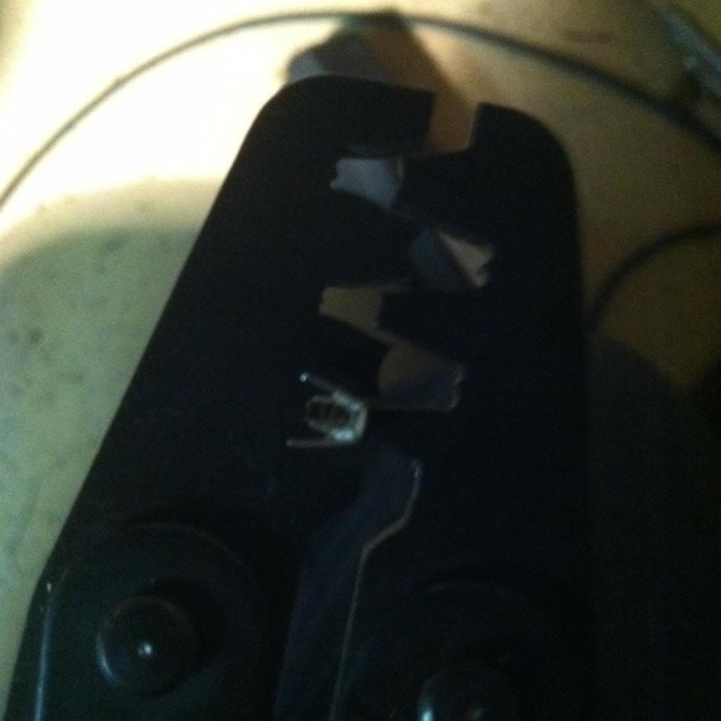 [/IMG]
[IMG]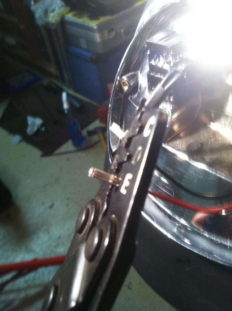 [/IMG]
[IMG]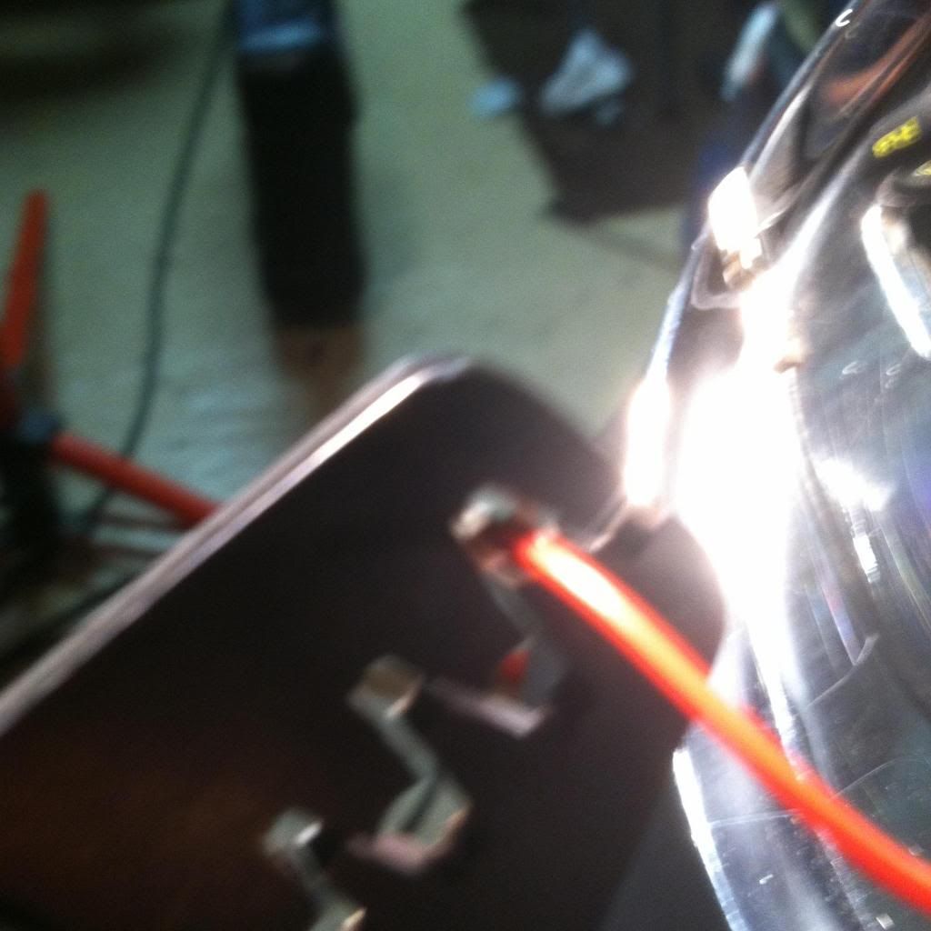 [/IMG]
[IMG]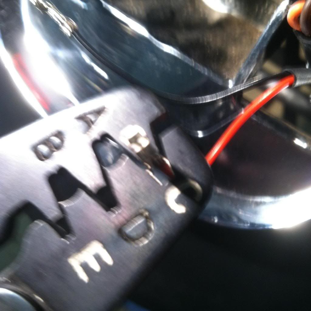 [/IMG]
[IMG]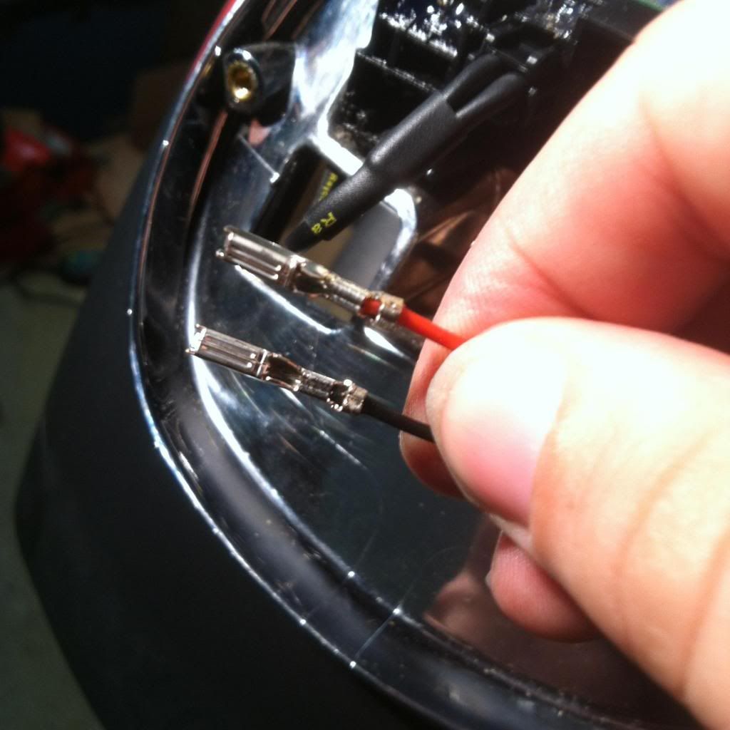 [/IMG]
Now that you are done crimping and adding heat shrink to the wires its time to install them into the 2 place amp connector. with the secondary lock facing you push the black wire into left part of the connector till you hear it click then do the same for the red wire. once both are in place close the secondary lock dab on some dielectric grease on the connector and plug it back into the circuit board in the tail light assembly. rinse and repeat for the other side.
after the strut lights are both plugged in reinstall the tail light make sure every thing works before installing your load load equalizer.
If you have done everything correctly they should look like this
[IMG]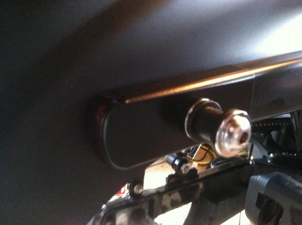 [/IMG]
And this
[IMG]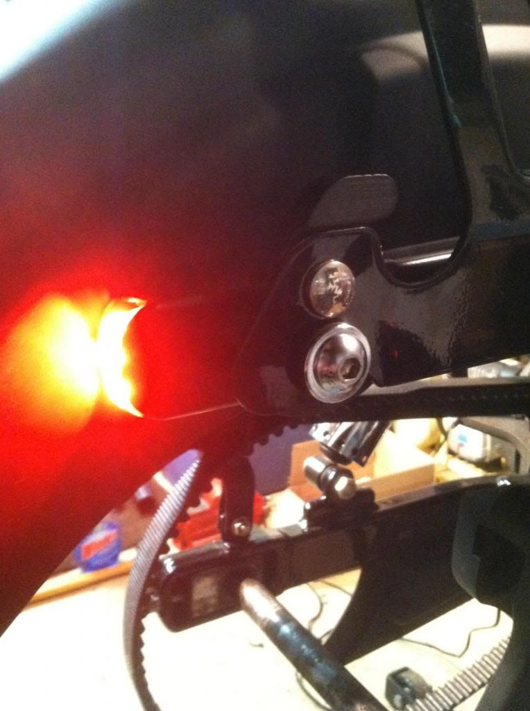 [/IMG]
And your tools will look something look like this
[IMG]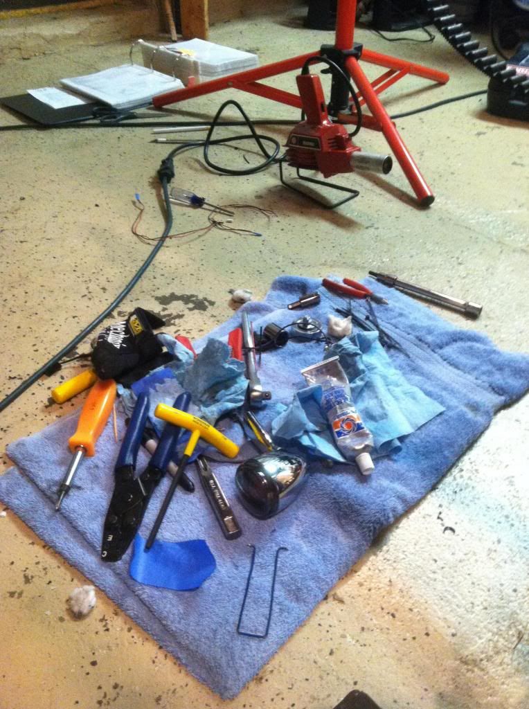 [/IMG]
I will go over installing the Badlands Plug-in Style Run, Brake & Turn Signal Module in the next part of this write up.
Will add pics as soon as photobucket stops craping out!
Tools Needed for this job:
Wire cutters
wire stripers
terminal crimper
Heat gun (not wife's blow dryer won't get hot enough to shrink DR25)
Small flat blade screw driver
phillips head screw driver
socket wrench
Inch pound torque wrench (not pictured)
7/32 allen wrench
7/32 allen socket
5/64 allen wrench
1/2" socket
T45 socket
3/8-16 thread chasers (not a cutting taps)
Mud Amp conncetor pick tool
straw from wd-40 can
scissors
X acto knife
China marker
Sharpie
Dielectric grease
Blue painters tape
Loctite 243
Small zip ties
[IMG]
 [/IMG]
Start by removing the rear wheel
The shop manual said to disconnect the negative battery terminal I didn't but that is up to you.
Next remove the tail light assembly from its base, disconnect the tail light connector and set it off to the side.
[IMG]
 [/IMG]
Now disconnect the turn signal wiring (2 place amp connector) using a small flat blade screw driver depress the tab on the connector and gently pull it free.
[IMG]
 [/IMG]
Once the wiring disconnected remove the turn signal housing and stand off by removing the bolts with a 1/2" socket these can be wrapped in soft cloth, put on Ebay or thrown in the trash as they will not be used for this install.
[IMG]
 [/IMG]
Now that the turn signals have been removed you will want to only work on one side at a time.
my shop lights were already set up on the left side of the bike so thats where I started
begin by loosening the torx 45 bolt on the strut cover be sure to keep the fender bracket from falling by holding it as remove the bolt or using some blue tape to keep it in place.
[IMG]
 [/IMG]
With the torx bolt removed carefully remove the fender bracket and chuck it in the same place the turn signals wound up.
[IMG]
 [/IMG]
Next replace the stock fender bracket with the one from your docking hardware or saddlebag kit.
If your are not going to run bags or detachable accessories, you need to buy or a make fender brackets with 3/8-16 threads.
I didn't like any of the harley offerings so I took the brackets from the wide tire kit (PN: 59514-06) to a local fabricator (47 Industries in Raritan, NJ) and had some 3/8-16 top hat bungs welded in place.
[IMG]
 [/IMG]
Install the front most docking point with tapered side facing in or torx bolt (if you're not installing the docking stuff) into the new fender bracket. These will only need to be hand tight for right now.
[IMG]
 [/IMG]
Before you send the strut lights out to the powder coater or rattle can them in your shed,
you will want to remove the LEDs and do a test fit.
This can be done by removing the set screws that hold them in place with an 5/64 allen wrench. It's much easier to see how to run the wires and how much clearance you have, If the LEDs and wires are out of the way.
[IMG]
 [/IMG]
As a side note these housings look almost identical, have no markings to differentiate the left from from the right and are real easy to get mixed up. Mine also didn't fit worth a damn. So i had to brake out the old dremel and take off some material to make these slide on a little smoother.
Now that the LEDs have been removed: Place the strut light housing over the strut cover do not press it on at this time, just hold it in place and with a free hand slide one of your 3/8-16" bolts through the slot in the housing and give it a few turns with your fingers so that the hosing is now held in place but away from the strut.
At this time you will want to pull the strut light housing toward the rear of the bike so that the slot is pressed against the bolt.
begin to slowly turn the bolt with your socket wrench in the same fashion you would use to close a bench vice this should be a smooth motion.
Note: If the bolt starts to bind or go in crooked as you tighten it. Stop you're installing the wrong one! remove it, set it aside and try the other one.
The correct housing should press it self over the strut cover as you slowly tighten the bolt, explained
in the steps above.
Now that you know your left from right and you're satisfied with fitment, remove the housing and label the inside so they read LH and RH with an engraving tool. (This will make your life easier during final assembly)
If you are running these back to the tail light like the stock ones apply 19" or 20" of DR-25 heat shrink to the wiring. With your heat gun shrink all but the last 2" or 3" i learned the hard way that the heat gun will fuse the wire insulators and the mil spec heat shrink to each other making it damn near impossible to cut and strip back if its too long.
better method would be to run the wires without the heat shrink cut them to length, remove them then add the heat shrink .
The reason I chose Raychem DR-25 over run of the mill heat shrink or even the PVC verity is it's flexibility and resistance to chemicals and abrasion. these wires have to make a few tight turns on this install so I didn't want anything that would kink or bunch up when running it between the strut and the fender. Additionally i wanted to beef up the little @ss 20 gauge wires for my own peace of mind.
Now that you have the wires cut to length and Applied heat shrink to them, reinstall the LEDs back into the strut light housing, it's time to start routing your wires. I took a tip from forum member FenceSC who was nice enough to take one of his apart to show me how he ran his wires.
Take some blue tape and wrap the bare end of the wire so you don't muck up the ends as you run them through the struts.
Starting from the bottom of the strut thread the wire between it and the fender just forward of the bolt so that the wire forms lose happy face (4-6" loop) next you will loop the wire
down and through the hole in the fender that was formerly used by the stock wiring.
[IMG]
 [/IMG]
Now that you have everything routed loosely begin neatening things by pulling the wire from inside the fender as you slowly feed wire from the other side.
[IMG]
 [/IMG]
keep pulling the wire till you're left with a loop small enough to hide behind the strut and the alloy art light housing. carefully begin to tighten the 3/8-16 bolt being sure not to pinch the wire between the housing and the fender.
I used the straw from a WD-40 can to push the wires in place before the last few turns of the bolt. you really want to make sure that the wires are not being pinched by the strut light housing, the strut or fender.
After you get the strut light housing pressed onto the cover, place strip of blue tape across the housing to help keep it in place. Now remove 3/8-16 bolt installed in the previous step apply a small drop or 2 of blue loctite and torque it to 12-18 FT LBS
Now remove the front most torx bolt or docking point installed earlier apply the same amount of loctite to this bolt as you did to the bolt in the previous step reinstall to and torque it to spec (12-18 FT LBS).
At this time you will want to neaten up your wiring securing it with the wire clips located under the fender then pass the wires though the square allocations in the tail light base.
I try to avoid cutting factory wires when ever possible and i don't trust solder splices
so I bought the proper amp terminals (73191-96) from the dealer and $25 crimper from ebay if you've never crimped any connectors before buy a few more then you need to do the job cause you will mess them up. the crimper I used had 5 different sized dies labeled A-E.
After striping back a small amount of the insulator, I used the E die to crimp the conductor portion of the terminal and the C die to crimp insulator/strain relief portion of the terminal. after this was done i added more DR-25 heat shrink to the wires to give the secondary lock of the amp connector (73152-96BK) a little more to hold onto.
[IMG]
 [/IMG]
[IMG]
 [/IMG]
[IMG]
 [/IMG]
[IMG]
 [/IMG]
[IMG]
 [/IMG]
Now that you are done crimping and adding heat shrink to the wires its time to install them into the 2 place amp connector. with the secondary lock facing you push the black wire into left part of the connector till you hear it click then do the same for the red wire. once both are in place close the secondary lock dab on some dielectric grease on the connector and plug it back into the circuit board in the tail light assembly. rinse and repeat for the other side.
after the strut lights are both plugged in reinstall the tail light make sure every thing works before installing your load load equalizer.
If you have done everything correctly they should look like this
[IMG]
 [/IMG]
And this
[IMG]
 [/IMG]
And your tools will look something look like this
[IMG]
 [/IMG]
I will go over installing the Badlands Plug-in Style Run, Brake & Turn Signal Module in the next part of this write up.
Last edited by Peter Black; 05-30-2014 at 05:45 PM.
#2
05-28-2014, 08:29 PM
Intermediate
Join Date: Oct 2013
Location: Texas
Posts: 26
Likes: 0
Received 0 Likes
on
0 Posts
#3
05-28-2014, 09:16 PM
#4
05-30-2014, 04:15 AM
Advanced
Join Date: Mar 2012
Location: Stuttgart, Germany - APO
Posts: 86
Likes: 0
Received 0 Likes
on
0 Posts
#5
05-30-2014, 10:06 AM
Install them first and see what happens. you can always order one later
#7
06-21-2015, 11:52 AM

4th Gear
What gauge is the wires for the new fender strut lights? Mine was so small that I couldn't crimp oem style connectors in to the amp connector. And solder melted them. Not impressed with the tiny wiring with the alloy art turn signals. Plus overpaid for them! Also did you modify anything to make the wiring fit. So it didn't get pinched
Alloy Art strut lights & docking points installed on 07 Dyna W/Stupid 180/55-18 Tire
Will add pics as soon as photobucket stops craping out!
Tools Needed for this job:
Wire cutters
wire stripers
terminal crimper
Heat gun (not wife's blow dryer won't get hot enough to shrink DR25)
Small flat blade screw driver
phillips head screw driver
socket wrench
Inch pound torque wrench (not pictured)
7/32 allen wrench
7/32 allen socket
5/64 allen wrench
1/2" socket
T45 socket
3/8-16 thread chasers (not a cutting taps)
Mud Amp conncetor pick tool
straw from wd-40 can
scissors
X acto knife
China marker
Sharpie
Dielectric grease
Blue painters tape
Loctite 243
Small zip ties
[IMG][/IMG]
Start by removing the rear wheel
The shop manual said to disconnect the negative battery terminal I didn't but that is up to you.
Next remove the tail light assembly from its base, disconnect the tail light connector and set it off to the side.
[IMG][/IMG]
Now disconnect the turn signal wiring (2 place amp connector) using a small flat blade screw driver depress the tab on the connector and gently pull it free.
[IMG][/IMG]
Once the wiring disconnected remove the turn signal housing and stand off by removing the bolts with a 1/2" socket these can be wrapped in soft cloth, put on Ebay or thrown in the trash as they will not be used for this install.
[IMG][/IMG]
Now that the turn signals have been removed you will want to only work on one side at a time.
my shop lights were already set up on the left side of the bike so thats where I started
begin by loosening the torx 45 bolt on the strut cover be sure to keep the fender bracket from falling by holding it as remove the bolt or using some blue tape to keep it in place.
[IMG][/IMG]
With the torx bolt removed carefully remove the fender bracket and chuck it in the same place the turn signals wound up.
[IMG][/IMG]
Next replace the stock fender bracket with the one from your docking hardware or saddlebag kit.
If your are not going to run bags or detachable accessories, you need to buy or a make fender brackets with 3/8-16 threads.
I didn't like any of the harley offerings so I took the brackets from the wide tire kit (PN: 59514-06) to a local fabricator (47 Industries in Raritan, NJ) and had some 3/8-16 top hat bungs welded in place.
[IMG][/IMG]
Install the front most docking point with tapered side facing in or torx bolt (if you're not installing the docking stuff) into the new fender bracket. These will only need to be hand tight for right now.
[IMG][/IMG]
Before you send the strut lights out to the powder coater or rattle can them in your shed,
you will want to remove the LEDs and do a test fit.
This can be done by removing the set screws that hold them in place with an 5/64 allen wrench. It's much easier to see how to run the wires and how much clearance you have, If the LEDs and wires are out of the way.
[IMG][/IMG]
As a side note these housings look almost identical, have no markings to differentiate the left from from the right and are real easy to get mixed up. Mine also didn't fit worth a damn. So i had to brake out the old dremel and take off some material to make these slide on a little smoother.
Now that the LEDs have been removed: Place the strut light housing over the strut cover do not press it on at this time, just hold it in place and with a free hand slide one of your 3/8-16" bolts through the slot in the housing and give it a few turns with your fingers so that the hosing is now held in place but away from the strut.
At this time you will want to pull the strut light housing toward the rear of the bike so that the slot is pressed against the bolt.
begin to slowly turn the bolt with your socket wrench in the same fashion you would use to close a bench vice this should be a smooth motion.
Note: If the bolt starts to bind or go in crooked as you tighten it. Stop you're installing the wrong one! remove it, set it aside and try the other one.
The correct housing should press it self over the strut cover as you slowly tighten the bolt, explained
in the steps above.
Now that you know your left from right and you're satisfied with fitment, remove the housing and label the inside so they read LH and RH with an engraving tool. (This will make your life easier during final assembly)
If you are running these back to the tail light like the stock ones apply 19" or 20" of DR-25 heat shrink to the wiring. With your heat gun shrink all but the last 2" or 3" i learned the hard way that the heat gun will fuse the wire insulators and the mil spec heat shrink to each other making it damn near impossible to cut and strip back if its too long.
better method would be to run the wires without the heat shrink cut them to length, remove them then add the heat shrink .
The reason I chose Raychem DR-25 over run of the mill heat shrink or even the PVC verity is it's flexibility and resistance to chemicals and abrasion. these wires have to make a few tight turns on this install so I didn't want anything that would kink or bunch up when running it between the strut and the fender. Additionally i wanted to beef up the little @ss 20 gauge wires for my own peace of mind.
Now that you have the wires cut to length and Applied heat shrink to them, reinstall the LEDs back into the strut light housing, it's time to start routing your wires. I took a tip from forum member FenceSC who was nice enough to take one of his apart to show me how he ran his wires.
Take some blue tape and wrap the bare end of the wire so you don't muck up the ends as you run them through the struts.
Starting from the bottom of the strut thread the wire between it and the fender just forward of the bolt so that the wire forms lose happy face (4-6" loop) next you will loop the wire
down and through the hole in the fender that was formerly used by the stock wiring.
[IMG][/IMG]
Now that you have everything routed loosely begin neatening things by pulling the wire from inside the fender as you slowly feed wire from the other side.
[IMG][/IMG]
keep pulling the wire till you're left with a loop small enough to hide behind the strut and the alloy art light housing. carefully begin to tighten the 3/8-16 bolt being sure not to pinch the wire between the housing and the fender.
I used the straw from a WD-40 can to push the wires in place before the last few turns of the bolt. you really want to make sure that the wires are not being pinched by the strut light housing, the strut or fender.
After you get the strut light housing pressed onto the cover, place strip of blue tape across the housing to help keep it in place. Now remove 3/8-16 bolt installed in the previous step apply a small drop or 2 of blue loctite and torque it to 12-18 FT LBS
Now remove the front most torx bolt or docking point installed earlier apply the same amount of loctite to this bolt as you did to the bolt in the previous step reinstall to and torque it to spec (12-18 FT LBS).
At this time you will want to neaten up your wiring securing it with the wire clips located under the fender then pass the wires though the square allocations in the tail light base.
I try to avoid cutting factory wires when ever possible and i don't trust solder splices
so I bought the proper amp terminals (73191-96) from the dealer and $25 crimper from ebay if you've never crimped any connectors before buy a few more then you need to do the job cause you will mess them up. the crimper I used had 5 different sized dies labeled A-E.
After striping back a small amount of the insulator, I used the E die to crimp the conductor portion of the terminal and the C die to crimp insulator/strain relief portion of the terminal. after this was done i added more DR-25 heat shrink to the wires to give the secondary lock of the amp connector (73152-96BK) a little more to hold onto.
[IMG][/IMG]
[IMG][/IMG]
[IMG][/IMG]
[IMG][/IMG]
[IMG][/IMG]
Now that you are done crimping and adding heat shrink to the wires its time to install them into the 2 place amp connector. with the secondary lock facing you push the black wire into left part of the connector till you hear it click then do the same for the red wire. once both are in place close the secondary lock dab on some dielectric grease on the connector and plug it back into the circuit board in the tail light assembly. rinse and repeat for the other side.
after the strut lights are both plugged in reinstall the tail light make sure every thing works before installing your load load equalizer.
If you have done everything correctly they should look like this
[IMG][/IMG]
And this
[IMG][/IMG]
And your tools will look something look like this
[IMG][/IMG]
I will go over installing the Badlands Plug-in Style Run, Brake & Turn Signal Module in the next part of this write up.
Will add pics as soon as photobucket stops craping out!
Tools Needed for this job:
Wire cutters
wire stripers
terminal crimper
Heat gun (not wife's blow dryer won't get hot enough to shrink DR25)
Small flat blade screw driver
phillips head screw driver
socket wrench
Inch pound torque wrench (not pictured)
7/32 allen wrench
7/32 allen socket
5/64 allen wrench
1/2" socket
T45 socket
3/8-16 thread chasers (not a cutting taps)
Mud Amp conncetor pick tool
straw from wd-40 can
scissors
X acto knife
China marker
Sharpie
Dielectric grease
Blue painters tape
Loctite 243
Small zip ties
[IMG]
[/IMG]Start by removing the rear wheel
The shop manual said to disconnect the negative battery terminal I didn't but that is up to you.
Next remove the tail light assembly from its base, disconnect the tail light connector and set it off to the side.
[IMG]
[/IMG]Now disconnect the turn signal wiring (2 place amp connector) using a small flat blade screw driver depress the tab on the connector and gently pull it free.
[IMG]
[/IMG]Once the wiring disconnected remove the turn signal housing and stand off by removing the bolts with a 1/2" socket these can be wrapped in soft cloth, put on Ebay or thrown in the trash as they will not be used for this install.
[IMG]
[/IMG]Now that the turn signals have been removed you will want to only work on one side at a time.
my shop lights were already set up on the left side of the bike so thats where I started
begin by loosening the torx 45 bolt on the strut cover be sure to keep the fender bracket from falling by holding it as remove the bolt or using some blue tape to keep it in place.
[IMG]
[/IMG]With the torx bolt removed carefully remove the fender bracket and chuck it in the same place the turn signals wound up.
[IMG]
[/IMG]Next replace the stock fender bracket with the one from your docking hardware or saddlebag kit.
If your are not going to run bags or detachable accessories, you need to buy or a make fender brackets with 3/8-16 threads.
I didn't like any of the harley offerings so I took the brackets from the wide tire kit (PN: 59514-06) to a local fabricator (47 Industries in Raritan, NJ) and had some 3/8-16 top hat bungs welded in place.
[IMG]
[/IMG]Install the front most docking point with tapered side facing in or torx bolt (if you're not installing the docking stuff) into the new fender bracket. These will only need to be hand tight for right now.
[IMG]
[/IMG]Before you send the strut lights out to the powder coater or rattle can them in your shed,
you will want to remove the LEDs and do a test fit.
This can be done by removing the set screws that hold them in place with an 5/64 allen wrench. It's much easier to see how to run the wires and how much clearance you have, If the LEDs and wires are out of the way.
[IMG]
[/IMG]As a side note these housings look almost identical, have no markings to differentiate the left from from the right and are real easy to get mixed up. Mine also didn't fit worth a damn. So i had to brake out the old dremel and take off some material to make these slide on a little smoother.
Now that the LEDs have been removed: Place the strut light housing over the strut cover do not press it on at this time, just hold it in place and with a free hand slide one of your 3/8-16" bolts through the slot in the housing and give it a few turns with your fingers so that the hosing is now held in place but away from the strut.
At this time you will want to pull the strut light housing toward the rear of the bike so that the slot is pressed against the bolt.
begin to slowly turn the bolt with your socket wrench in the same fashion you would use to close a bench vice this should be a smooth motion.
Note: If the bolt starts to bind or go in crooked as you tighten it. Stop you're installing the wrong one! remove it, set it aside and try the other one.
The correct housing should press it self over the strut cover as you slowly tighten the bolt, explained
in the steps above.
Now that you know your left from right and you're satisfied with fitment, remove the housing and label the inside so they read LH and RH with an engraving tool. (This will make your life easier during final assembly)
If you are running these back to the tail light like the stock ones apply 19" or 20" of DR-25 heat shrink to the wiring. With your heat gun shrink all but the last 2" or 3" i learned the hard way that the heat gun will fuse the wire insulators and the mil spec heat shrink to each other making it damn near impossible to cut and strip back if its too long.
better method would be to run the wires without the heat shrink cut them to length, remove them then add the heat shrink .
The reason I chose Raychem DR-25 over run of the mill heat shrink or even the PVC verity is it's flexibility and resistance to chemicals and abrasion. these wires have to make a few tight turns on this install so I didn't want anything that would kink or bunch up when running it between the strut and the fender. Additionally i wanted to beef up the little @ss 20 gauge wires for my own peace of mind.
Now that you have the wires cut to length and Applied heat shrink to them, reinstall the LEDs back into the strut light housing, it's time to start routing your wires. I took a tip from forum member FenceSC who was nice enough to take one of his apart to show me how he ran his wires.
Take some blue tape and wrap the bare end of the wire so you don't muck up the ends as you run them through the struts.
Starting from the bottom of the strut thread the wire between it and the fender just forward of the bolt so that the wire forms lose happy face (4-6" loop) next you will loop the wire
down and through the hole in the fender that was formerly used by the stock wiring.
[IMG]
[/IMG]Now that you have everything routed loosely begin neatening things by pulling the wire from inside the fender as you slowly feed wire from the other side.
[IMG]
[/IMG]keep pulling the wire till you're left with a loop small enough to hide behind the strut and the alloy art light housing. carefully begin to tighten the 3/8-16 bolt being sure not to pinch the wire between the housing and the fender.
I used the straw from a WD-40 can to push the wires in place before the last few turns of the bolt. you really want to make sure that the wires are not being pinched by the strut light housing, the strut or fender.
After you get the strut light housing pressed onto the cover, place strip of blue tape across the housing to help keep it in place. Now remove 3/8-16 bolt installed in the previous step apply a small drop or 2 of blue loctite and torque it to 12-18 FT LBS
Now remove the front most torx bolt or docking point installed earlier apply the same amount of loctite to this bolt as you did to the bolt in the previous step reinstall to and torque it to spec (12-18 FT LBS).
At this time you will want to neaten up your wiring securing it with the wire clips located under the fender then pass the wires though the square allocations in the tail light base.
I try to avoid cutting factory wires when ever possible and i don't trust solder splices
so I bought the proper amp terminals (73191-96) from the dealer and $25 crimper from ebay if you've never crimped any connectors before buy a few more then you need to do the job cause you will mess them up. the crimper I used had 5 different sized dies labeled A-E.
After striping back a small amount of the insulator, I used the E die to crimp the conductor portion of the terminal and the C die to crimp insulator/strain relief portion of the terminal. after this was done i added more DR-25 heat shrink to the wires to give the secondary lock of the amp connector (73152-96BK) a little more to hold onto.
[IMG]
[/IMG][IMG]
[/IMG][IMG]
[/IMG][IMG]
[/IMG][IMG]
[/IMG]Now that you are done crimping and adding heat shrink to the wires its time to install them into the 2 place amp connector. with the secondary lock facing you push the black wire into left part of the connector till you hear it click then do the same for the red wire. once both are in place close the secondary lock dab on some dielectric grease on the connector and plug it back into the circuit board in the tail light assembly. rinse and repeat for the other side.
after the strut lights are both plugged in reinstall the tail light make sure every thing works before installing your load load equalizer.
If you have done everything correctly they should look like this
[IMG]
[/IMG]And this
[IMG]
[/IMG]And your tools will look something look like this
[IMG]
[/IMG]I will go over installing the Badlands Plug-in Style Run, Brake & Turn Signal Module in the next part of this write up.
Trending Topics
#8
06-22-2015, 03:20 PM
What gauge is the wires for the new fender strut lights? Mine was so small that I couldn't crimp oem style connectors in to the amp connector. And solder melted them. Not impressed with the tiny wiring with the alloy art turn signals. Plus overpaid for them! Also did you modify anything to make the wiring fit. So it didn't get pinched
#9
10-02-2015, 11:37 AM

Ok I just read through EVERY post on this forum and this is by far the most popular and is the only one that explains with pictures, so Im going to post some info here. br>
I just bought a pair of Alloy Art fender strut LED lights from Revzilla. I missed the part in the description where it said they are SINGLE FUNCTION only so when they arrived I realized I would need to do some work to get them installed and have run/brake/turn available.
There are a million videos on youtube or in other places that explain how to wire in a resistor and two diodes, its not CRAZY complicated but Its not something I want to do so I decided to buy pre-wired set up from Custom Dynamics. They were $5 a piece plus shipping and are supposed to wire right in. For all those looking for a "how to" im going to post it all in similar fashion once I have everything up and running. (Hopefully the connectors show up in the next few days)
For some reason I cant add hyperlinks to this post (?) so Im just going to post some websites below:
Custom Dynamics https://www.customdynamics.com/plugz.htm --Go to the bottom of the page and you'll see
Dual Converter for Plugz� Item: TFC1 Price: $4.95 ea
These are what you need. You will need one for each light. Heres a pic of what they look like:
https://www.denniskirk.com/215701.sk...ad=45713354197
Here is a wiring diagram for installation. Page 3 shows a run/brake/turn application (just ignore the rest if this is what youre trying to accomplish)
https://www.customdynamics.com/instructions/plugz.pdf
Hopefully this helps some of you that are in the same boat as me. Good luck!

Thread
Thread Starter
Forum
Replies
Last Post
Cardstang
Dyna Glide Models
16
03-22-2015 08:33 PM
ncbeast
Ignition/Tuner/ECM/Fuel Injection
1
05-15-2009 06:25 AM