Harley Davidson Sportster: How to Replace Clutch Cable
The clutch cable connects the lever to the clutch disengagement assembly inside the transmission. The cable is made of braided wire for strength and flexibility. The cable must maintain a precise length between the lever and transmission, otherwise difficult shifting will result.
This article applies to the Harley Davidson Sportster.
The clutch cable uses two adjustment points to create or reduce slack in the cable. As the clutch wears, the cables tension reduces. The braided steel cable may also wear and stretch, further reducing the tension. Once the tension is reduced to a certain point, you'll notice a harshness as gears are selected. If the wear is severe enough to not disengage the clutch at all, shifting may not be possible.
Materials Needed
- T27 torx socket or wrench
- Block of wood
- Jack stand
- Torque wrench (in. lb.)
- Small flat head screwdriver
- 1/2" wrench
- 9/16" wrench
- Vaseline
- Blue Loctite
- Rubber gloves
- Safety glasses
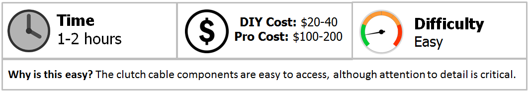
Step 1 – Remove the clutch inspection cover
To keep transmission fluid from falling out of the clutch cover opening, level your bike. For example, you can place the kickstand against a block of wood and use a jackstand to keep the opposite side from leaning. Refer to the article: Harley Davidson Sportster: How to Replace Transmission Fluid for instructions on re-filling the system. Remove the six T27 Torx screws from the clutch inspection cover.
Step 2 – Remove the clutch cable from the clutch lever
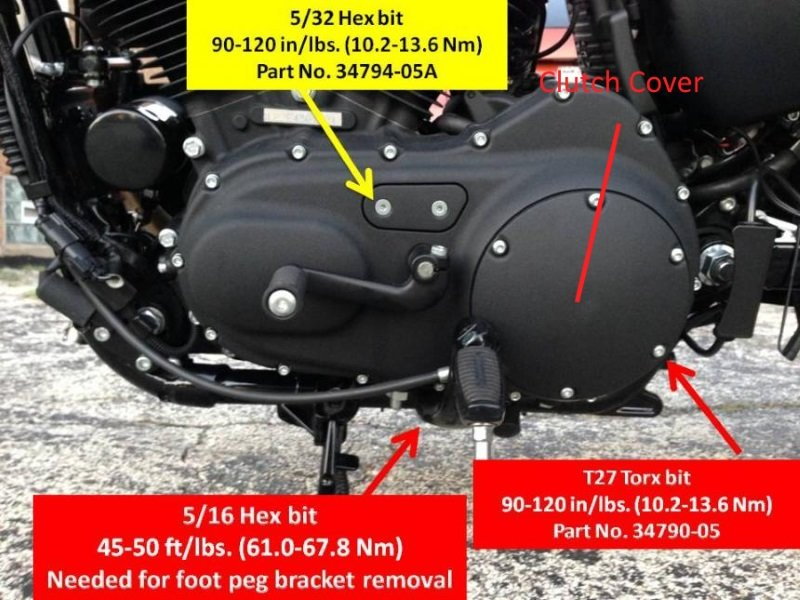
Remove any clutch cable holders from the bike's frame. These may clip onto the frame or bolt on. Follow the path of the cable from the lever to the clutch cover to locate the holders. Looking at the bottom of the clutch lever, locate the small circular clip. Remove the clip with a flat head screwdriver by prying the clip off the pin it surrounds. The pin can now be pushed up and out of the lever. Move halfway down the cable to locate the midway adjustment point. It may be covered by a rubber boot. Slide the boot up the cable and loosen the lock nut from the cable threads with a 9/16" and 1/2" wrench. Turn the cable nut clockwise up the threads to loosen the tension in the lever. Move back up to the lever and pull the cable away from the lever to take away the slack in the cable. This will expose the dowel on the cable and allow you to slide the cable/lever assembly out of the handle bars. Push down on the plastic pin to separate the cable from the lever.
Figure 2. The small clip holding the clutch cable pin to the handle bars. 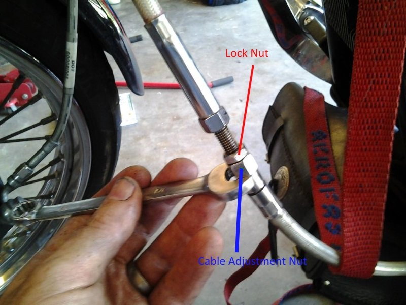
Figure 3. The clutch cable midpoint adjustment. 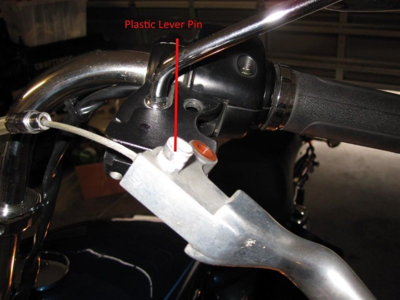
Figure 4. The plastic lever pin. 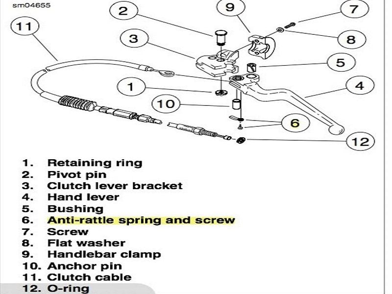
Figure 5. A diagram of the clutch lever assembly.
Step 3 – Remove the clutch cable from the coupling mechanism
Begin by creating slack in the clutch cable at the adjustment point closest to the transmission case. Loosen the lock nut and turn the adjustment nut clockwise. Looking into the components behind the clutch inspection cover, you'll first see a spring attached to a hex lockplate. Remove these from the assembly by pulling them outwards. Turn the adjusting screw CLOCKWISE with a flat head screwdriver to release the ramp and coupling mechanism. With the mechanism slid off of the adjusting screw, flip the mechanism 180 degrees then rotate it counter-clockwise 180 degrees to remove the cable from the mechanism. Move back to where the cable threads into the primary cover and remove it.

Figure 6. A diagram of the clutch cable inside the primary cover. 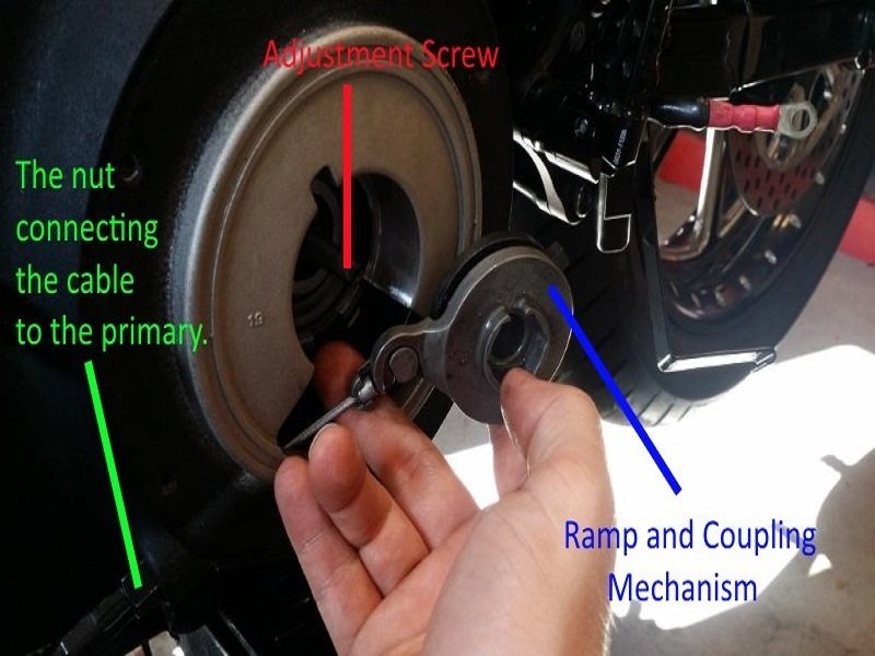
Figure 7. Removing the clutch cable from the ramp and coupling.
Step 4 – Install and adjust the new cable
Install the new cable to the lever first. Install the new cable onto the ramp and coupling mechanism and slide the mechanism over the adjustment screw. Make sure the slot in the primary cover lines up with the tab on the mechanism. Place the hex plate against the adjustment screw and thread the screw into the hex plate by turning the screw COUNTER-CLOCKWISE with a flat head screwdriver. Tighten the adjustment screw until it's snug then release it a quarter turn. Slide the spring onto the hex lock plate and place the quad ring gasket into the slot on the primary case. Refer to Step 1 if you need to adjust your transmission fluid level. You can use a small amount of Vaseline to hold the quad ring in the case while the primary cover is being installed. Install the primary cover by adding some blue Loctite to the six T27 screws and tightening them in a star pattern. Torque the screws to 100 in. lbs.
To adjust the cable at the lever end, pull on the cable where it connects to the lever and measure 1/16" of play. Adjust the cable nut at the midway adjustment point until 1/16" of play is attained.
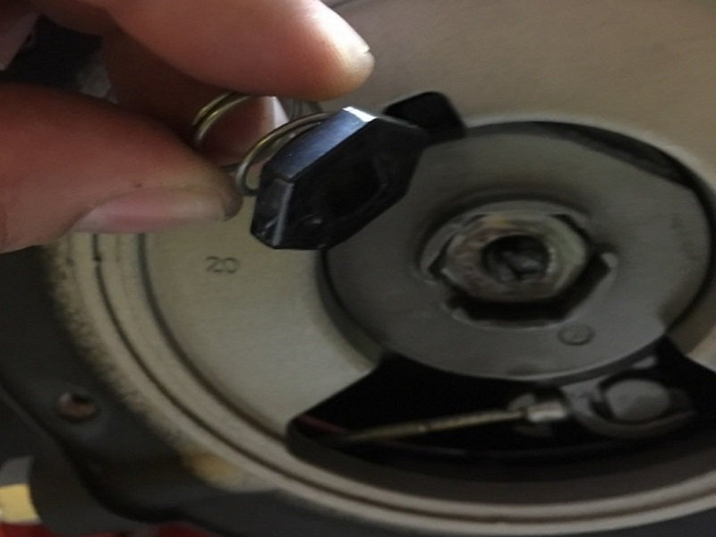
Figure 8. Installing the spring against the hex plate and over the adjusting screw. 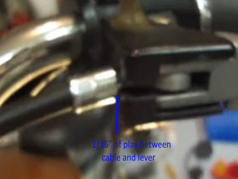
Figure 9. Adjusting the cable at the clutch lever.
Related Videos
-
Clutch Lever Change
-
Clutch Cable Replacement
-
Clutch Cable Replaced
Related Videos and Discussions
- Clutch Lever Change - Youtube.com
- Clutch Cable Replacement - Youtube.com
- Clutch Cable Replaced - Youtube.com
- Mod Thread 2013 48 - HDForums.com
- How to Remove Clutch Cable - HDForums.com