


How do you bypass a bank angle sensor on a twin cam
Does anyone know how to bypass the Bank Angle sensor wiring in a twin cam engine? Im in process of wiring up a softail frame with a 00 twin cam engine. Its going to be carbureted W/ single fire ignition system/ using a DYNA ignition. I posted in the custom section but thought I would post here to. Thanks all.
TOOLBOX
TOOLBOX

Banned
Joined: Jul 2006
Posts: 866
Likes: 1
From:
The bank angle takes a high voltage and cuts it down to a low voltage - the ignition coil uses a low voltage as a signal to operate - not tipped. When the sensor is activated, voltage goes higher and that is the signal not to operate. Some guys have used resistors - if you look at the wiring, you can make a bypass with a diode.
Thanks One_Screamin_Eagle, I apreciate the advice. I will look into doing that. Diode huh, using a restistor would just keep the voltage low @ all times, So to be able to bypass the circuit /angle sensor entirely with a loop wire? Thanks agian to the replay.
TOOLBOX
TOOLBOX
Road Captain
Joined: Sep 2005
Posts: 583
Likes: 5
From: Maine
A resister doesn't drop voltage, it drops current. A diode allows current to flow in one direction and not the other. Using either one of these independently or together will not accomplish what is suggested.
As mentioned in the other thread, I believe it is a 5 volt signal. If you want to try to bypass it, you will need a 5 volt power source. Building such and item will likely be larger than the BAS. It will also need to be built to withstand the adverse conditions associated with being on a motorcycle. Hate to sound like a broken record but the BAS is already built to these standards and will be reliable. It would be very easy to mount the small BAS near the ignition module and have minimal amounts of wires to run.
If you still want to build something that supply the signal, I would suggest using a LM7805 voltage regulator. You will also need a current limiting resister on the output. A 100k 1/4 watt resister should work. You will need to make 3 connections to the device, ground, 12 volts and signal to the ignition module. BTW, they are the same connections you would make to a BAS.
Here is a bike build that I did exactly what I am suggesting. https://www.hdforums.com/m_242003/tm.htm
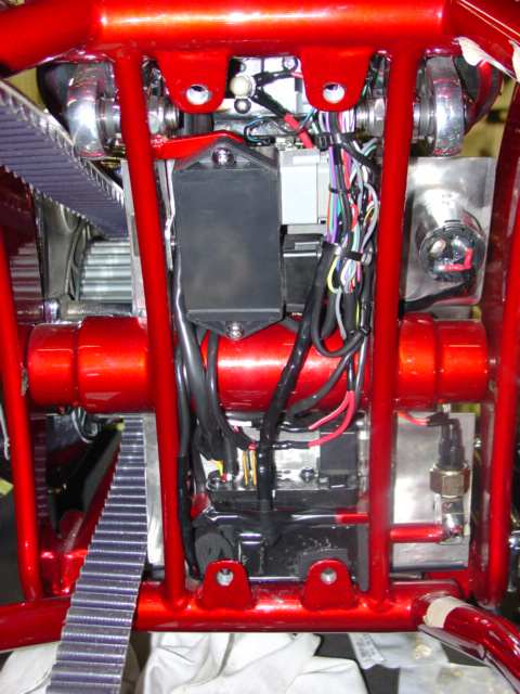
Here is a picture of the wiring when completed. The BAS is located on the back of the battery box. You can see the gray connector of the BAS right beside the red tab on the frame (right side). Note its location compared to the ignition module, about 1 inch above the gray connector on the ignition module.
As mentioned in the other thread, I believe it is a 5 volt signal. If you want to try to bypass it, you will need a 5 volt power source. Building such and item will likely be larger than the BAS. It will also need to be built to withstand the adverse conditions associated with being on a motorcycle. Hate to sound like a broken record but the BAS is already built to these standards and will be reliable. It would be very easy to mount the small BAS near the ignition module and have minimal amounts of wires to run.
If you still want to build something that supply the signal, I would suggest using a LM7805 voltage regulator. You will also need a current limiting resister on the output. A 100k 1/4 watt resister should work. You will need to make 3 connections to the device, ground, 12 volts and signal to the ignition module. BTW, they are the same connections you would make to a BAS.
Here is a bike build that I did exactly what I am suggesting. https://www.hdforums.com/m_242003/tm.htm
Here is a picture of the wiring when completed. The BAS is located on the back of the battery box. You can see the gray connector of the BAS right beside the red tab on the frame (right side). Note its location compared to the ignition module, about 1 inch above the gray connector on the ignition module.
Banned
Joined: Jul 2006
Posts: 866
Likes: 1
From:
Been there a long time ago and wired a doide in place of a sensor. Was years back so without digging through all the notes, can't remember specs. It worked because of the way the circuit is laid out. Thanks for the lecture on why it won't work, but it does.
Road Captain
Joined: Sep 2005
Posts: 583
Likes: 5
From: Maine
ORIGINAL: One_Screamin_Eagle
Been there a long time ago and wired a doide in place of a sensor. Was years back so without digging through all the notes, can't remember specs. It worked because of the way the circuit is laid out. Thanks for the lecture on why it won't work, but it does.
Been there a long time ago and wired a doide in place of a sensor. Was years back so without digging through all the notes, can't remember specs. It worked because of the way the circuit is laid out. Thanks for the lecture on why it won't work, but it does.
Have a Great day.
Road Captain
Joined: Sep 2005
Posts: 583
Likes: 5
From: Maine
ORIGINAL: One_Screamin_Eagle
The bank angle takes a high voltage and cuts it down to a low voltage - the ignition coil uses a low voltage as a signal to operate - not tipped. When the sensor is activated, voltage goes higher and that is the signal not to operate. Some guys have used resistors - if you look at the wiring, you can make a bypass with a diode.
The bank angle takes a high voltage and cuts it down to a low voltage - the ignition coil uses a low voltage as a signal to operate - not tipped. When the sensor is activated, voltage goes higher and that is the signal not to operate. Some guys have used resistors - if you look at the wiring, you can make a bypass with a diode.
The suggestion above, as I read it, is the signal to disable the ignition is a "hi" or 5 volts. And the signal that enables the ignition is a "Lo" or ground. If this is a the case, and I have not confirmed it, then pulling the signal for enable Lo would then turn on the ignition.
To confirm the ignition is enabled when the "ignition enable" pin is Lo, turn the bike on and check the voltage on the pin. If it reads 5 volts with nothing attached, then a Lo signal will probably enable it.
To do this a resister could be used. The resister value could vary considerably depending on the circuit in the ignition module. IMO, the highest resister value that pulls it Lo should be used. To test this, go to radio shack and buy an assortment of resisters. I would recommend 100K Ohm 1/4 watt, 10K Ohm 1/4 watt, 5K Ohm 1/4 watt and 1K Ohm 1/4 watt resisters. Starting with the highest value (100K), connect one end to the ignition enable pin on the ignition module (black connector, pin 10 I believe). Then connect the other end of the resister to ground. When you turn the bike on (run position) the signal at pin 10 should read zero volts (ground). If it does not then use the next lower value resister until it read 0 volts on the pin. Remember the resister is used to limit the amount of current draw on that signal so the higher the value, the less current draw.
Good luck and let us know if it works and what value resister you used.
Trending Topics
Banned
Joined: Jul 2006
Posts: 866
Likes: 1
From:
I believe the magic # is about .7 v to make it run
HD Forum Stories
The Best of Harley-Davidson for Lifelong Riders

8 Best Harley-Davidson Motorcycles Ever
Pouria Savadkouei
10 Worst Harley-Davidson Motorcycles Ever
Pouria Savadkouei
Killer Custom's Jail Break Is The Breakout That Refused to Blend In
Verdad Gallardo
Crazy Bunderbike Build Looks Amazing, But Is It Impossible to Ride?
Verdad Gallardo
Harley-Davidson Reveals Super Cool Cafe Racer Concept
Verdad Gallardo
Engraved Rebellion: Inside Bundnerbike's Glam Rock II
Verdad Gallardo
10 Motorcycles You Should Never Buy
Joe Kucinski
10 Things Harley-Davidson Needs to Fix in 2026
Verdad Gallardo
Southpaw Super Glide: A Left-Hand-Drive 1979 Harley FXE Built to Fit the Rider
Verdad Gallardo6th Gear
Joined: Jun 2018
Posts: 13
Likes: 0
From: Pomona
Sounds like you guys may know some things that can help me with a problem I'm having. I'm installing a Motogadget M.Unit Blue on my 2000 Dyna Wide Glide, and the bank angle sensor is causing me some confusion. Here's the link to my post on the subject:
https://www.hdforums.com/forum/dyna-...l#post17563488
I don't necessarily need to bypass the BAS ... though I wouldn't mind doing so.
https://www.hdforums.com/forum/dyna-...l#post17563488
I don't necessarily need to bypass the BAS ... though I wouldn't mind doing so.
Seasoned HDF Member


Joined: Aug 2008
Posts: 5,052
Likes: 993
what year machine are you talking about? is the harness you are using of the same vintage? if it isn't in the tsm/tssm it could be hacked. even the internal ones can be hacked but requires opening up the unit. basically asking if it is a compilation of parts.
although resistors do resist current, they do have a voltage drop across them, often, used in a comparator circuit.
although resistors do resist current, they do have a voltage drop across them, often, used in a comparator circuit.