Harley Davidson Sportster: Ignition Diagnostic Guide
The ignition system ignites the air/fuel mixture inside the combustion chamber. A spark occurs at the correct time to create optimum engine power. If you are experiencing no-starts, misfires, or poor acceleration, this article may help.
This article applies to the Harley Davidson Sportster (1995-2016).
The ignition system is tasked with correctly energizing the spark plug at the needed time during the combustion cycle. The crankshaft position sensor is used to determine where the engine's position is and when the plug will fire. Once this is known, the ignition module or E.C.M. sends power to the ignition coil. The coil increases the voltage and transfers the energy to the spark plug. This article will guide you step-by-step to diagnose each component, starting with the easiest/most common problems.
Materials Needed
- Multimeter
- SAE socket set with ratchet
- Phillips and flat head screwdrivers
- Needle nose pliers
- T-pins
- Spark tester
- Spark plug gapping tool
Always begin your diagnostics by checking for trouble codes. Refer to the article How to Obtain Diagnostic Trouble Codes.
One of the most common sources of electrical problems is the battery. Test the battery's state of charge and current capacity by reading Step 2 of the article Electrical Diagnostic Guide.
Step 1 – Check for spark
If no spark is present at the end of the spark plug wire, the air/fuel mixture cannot ignite.
To test for spark:
- Remove your spark plug wires from the spark plugs.
- Insert a spark tester into the wire and attach the tester to ground.
- Remove the fuel pump fuse. Refer to the article Fuse Box Information for fuse locations.
- Crank the engine and watch for spark.
- If spark is consistently present, the problem most likely lies with the spark plugs and you should continue to Step 2. If no spark is present, continue to Step 3.
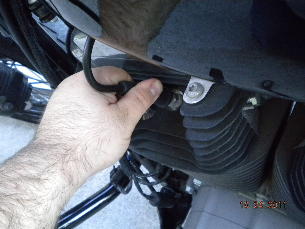
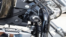
Figure 1. Pull and twist on the plug wire boot to remove it from the spark plug. 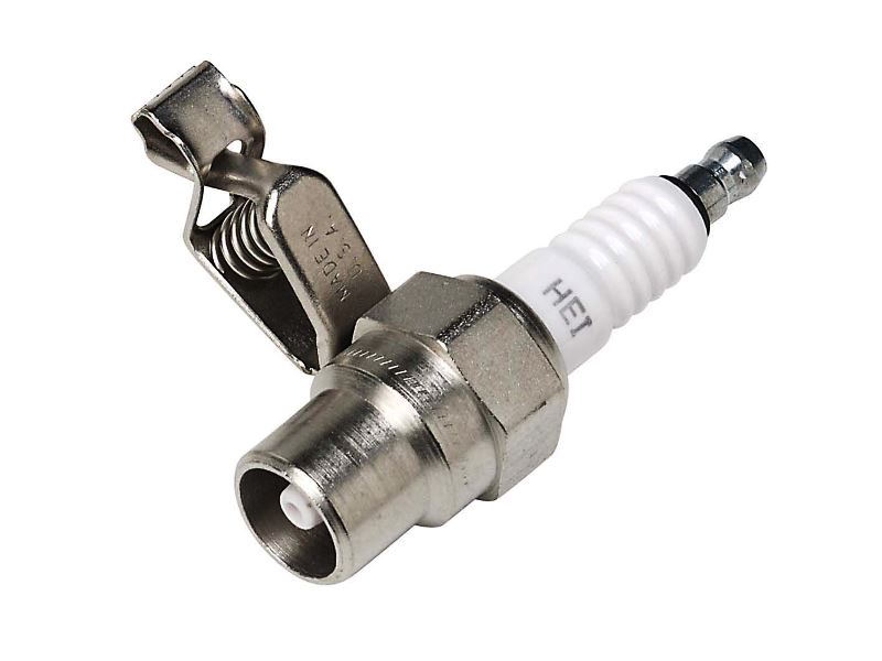
Figure 2. A spark tester.
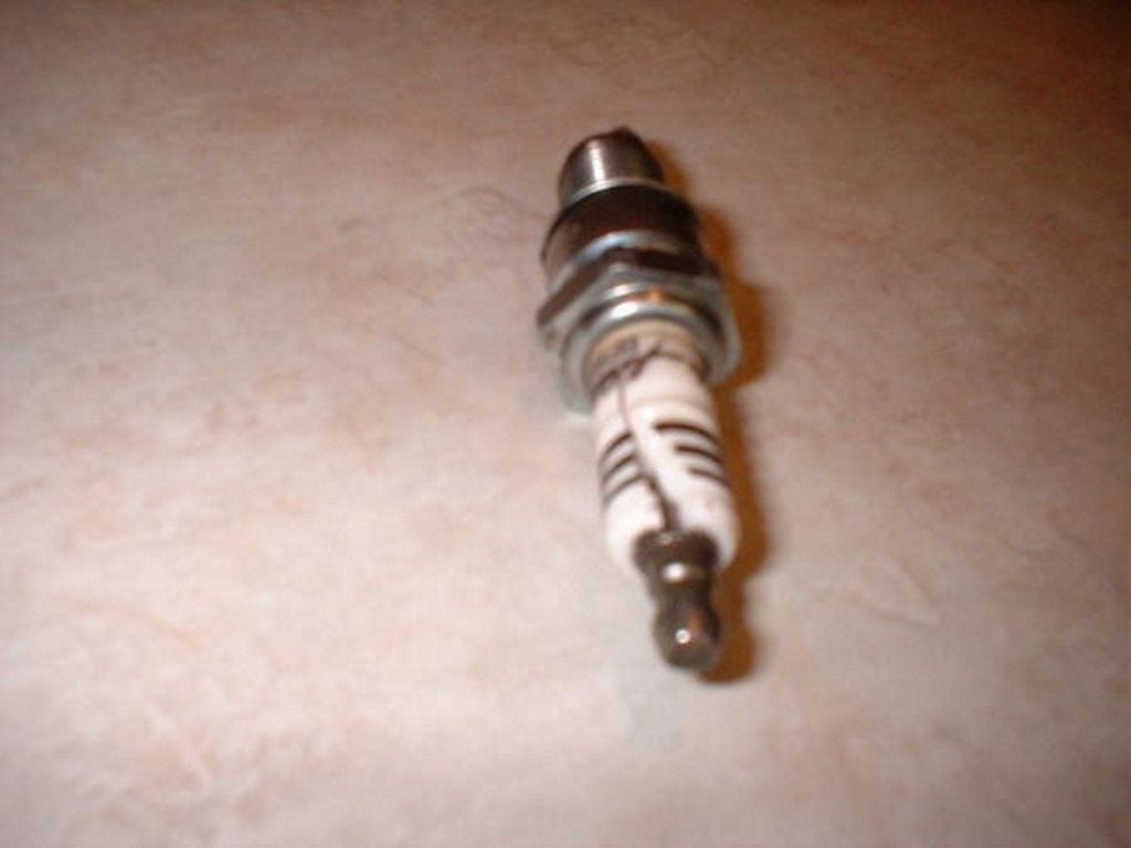
Step 2 – Inspect spark plugs
Spark plugs may not create a spark when the ceramic case is cracked, the electrode tip is broken, or the electrode is worn. If the engine has been running poorly for some time, the plugs may be covered in soot or fuel.
To check, clean, and replace the spark plugs, refer to the article How to Replace Spark Plugs and Plug Wires. Make sure the spark plug gap is near the factory specification.
Step 3 – Test the spark plug wires
Now that we know no spark is present from our test in Step 1, we can work from component to component in the ignition system, starting with the easiest. Remove the spark plug wires from the ignition coil and spark plugs. If these wires are different lengths, you may want to mark them. Inspect the wires for cracks and carbon deposits on the metal tips. Replace if necessary.
To test the spark plug wires:
- Set your multimeter to read ohms.
- Place your multimeter probes at each end of the spark plug wire.
- Measure the spark plug wires resistance level. A normal reading can be between 1 and 20,000 ohms. The reading "OL" stands for open lead and indicates the wire is bad.
Step 4 – Test the ignition coil
An ignition coil contains two sets of copper winding: the primary and the secondary. When current is sent to the ignition coil from the ignition module or E.C.M., the primary winding energizes and creates a strong magnetic field. The secondary winding increases the voltage as the magnetic field is created and sends a high energy spark to the spark plug. Problems with primary or secondary winding will not allow a conductive path for current and the spark plugs will not work.
To test and inspect the ignition coil:
- Visually inspect the ignition coil for cracks, hot spots (melted areas), and carbon buildup. Replace if necessary.
- Measure the resistance of the primary winding. Set your meter to read ohms and place your red probe on the positive post of the coil. Place the black probe on the negative post. Your reading should be between three and four ohms.
- Measure the resistance of the secondary winding. Place your red probe on the positive post of the coil. Place the black probe on the spark plug wire terminal. Your reading should be between 10,000 and 20,000 ohms.
Later model Sportsters use a wiring connector instead of individual posts on the coil. To measure this styles resistance, you'll need to unplug the connector and measure the resistance at the four prongs on the coil. You'll need a copy of your year's service manual or wiring diagrams from your local Harley dealership for prong locations.
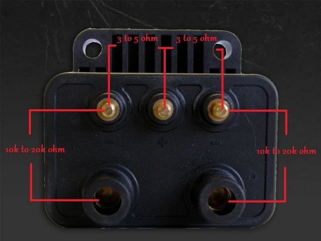
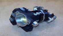
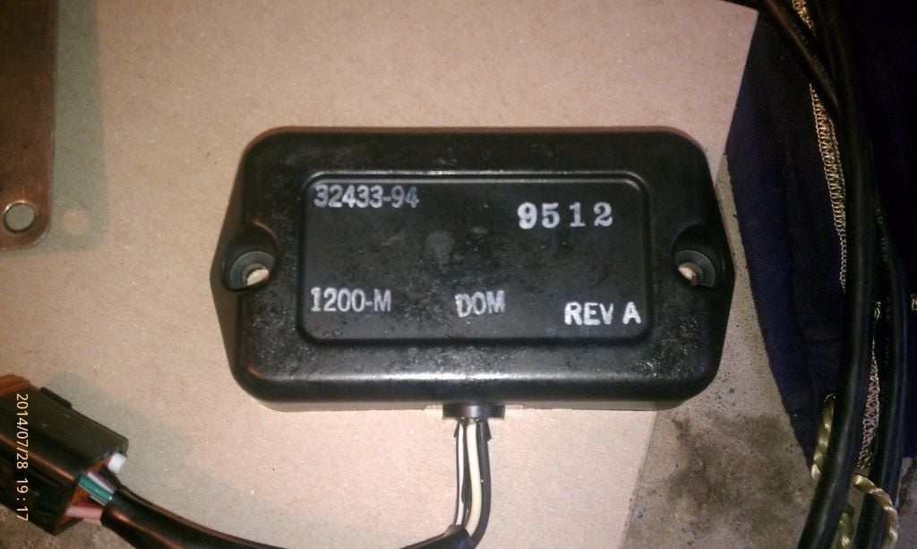
Figure 4. The ignition coil on earlier model Sportsters. 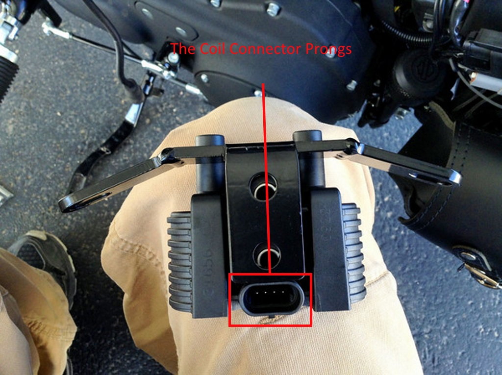
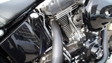
Figure 5. The ignition coil on later model Sportsters.
Step 5 – Test the crankshaft position sensor
The crankshaft position sensor is used to determine the crankshaft's speed and position. The E.C.M. or ignition module uses this information to correctly time the spark at the spark plug with the piston. As the reluctor wheel on the crankshaft rotates, a voltage is created in the sensor that the E.C.M. interprets as crankshaft position. The sensor itself can be faulty or the wiring between the sensor and E.C.M. can be the problem.
To test the crankshaft position sensor:
- Probe the connector wiring at the sensor. Small metal T-pins work great for this. Make sure the T-pins do not come into contact with each other.
- Clip or hold the multimeter probes to each T-pin.
- Set your meter to read AC milli-volts.
- Record the reading while cranking the engine. A normal reading is 0.3 volts AC. At idle, the reading should be closer to one volt AC
If your unable to crank the engine:
- Unbolt the sensor from the engine.
- Measure the sensors resistance by connecting your meter's probes to each sensor prong.
- The resistance should be between 100 and 600 ohms.
If the voltage readings at the sensor were not within specification, you'll need to check the wiring between the sensor and ignition module/E.C.M. To test the crankshaft position sensor wiring:
For 2004 to 2006 Sportsters:
- Measure the continuity between the sensor's red wire and ignition module terminal 8.
- Measure the continuity between the sensor's black wire and ignition module terminal 9.
- Continuity should be present on both wires.
For 2007 to 2013 Sportsters:
- Measure the continuity between the sensor's red wire and E.C.M. position 30.
- Measure the continuity between the sensor's black wire and E.C.M. position 12.
- Continuity should be present on both wires.
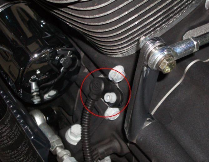
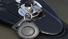
Figure 6. The crankshaft position sensor location.
Step 6 – Test the I.C.M. or E.C.M.
The I.C.M. (ignition control module) was used on Sportsters before the year 2007. After 2007, the module became integrated into the E.C.M. (electronic control module). These modules contain internal circuitry found on most computer motherboards. The voltages used on these circuits are very small and hard to test. The easiest way to test a computer module is by verifying its power and ground connections are correct.
To test your module's power and grounds:
- Find the wiring diagram for your year's Sportster in a service manual, or from your local Harley dealership.
- Locate the power and ground wires.
- Measure the power wire's voltage. Set your meter to read DC volts. Place the red probe on the power wire at the ignition module/E.C.M. and the black wire on a good ground; 12 volts should be present with the ignition in the on/run position.
- Measure the ground wire's voltage. Place the red probe on the ground wire at the ignition module/E.C.M., and the back probe on battery positive; 12 volts should be present with the ignition in the on/run position.
- To verify the power wire is undamaged, measure the voltage drop on the power wire by placing the red probe near the power wire's connection of the battery and the black probe on the power wire near the ignition module/ E.C.M. If the voltage drop is less than 0.5 volts, the wire is okay.
- Do the same test for the ground wire. Place the red probe on the ground wire's connection closest to the battery and the black probe on the ground wire at the ignition module. If the voltage drop is less than 0.5 volts, the wire is okay.
Related Discussions
- Sportster Ignition Problems- HDForums.com
- Ignition Problems Maybe - HDForums.com
- Sporster Iginition Issues - HDForums.com