Harley Davidson Touring: How to Replace Parking and Tail Lights with LEDs
Changing out the OEM brake lights and tail lights with super bright LEDs is a great way to make sure you are visible no matter the time of day you ride.
This article applies to the Harley Davidson Touring (1991-2015).
Inattentive drivers are our worst nightmare when we ride. With so many distractions on the road, from loud music to cell phones, we have to constantly stay vigilant every time we saddle up. It's easy to get comfortable and let your guard down, and one way to help you stay safe is to add lighting modifications to your Harley. This not only makes your bike uniquely your own, it can help a great deal with keeping the rubber side down. Adding super bright LED rear tail lights and turn signals is a great modification that is easy to do, looks awesome and really helps get you noticed from the traffic behind you. Changing over the front lights is very similar, and will help you to be seen from the front, too. Plus it will make your bike different, which should make you ever happier every time you get to take your baby out on the boulevard.
Materials Needed
- Phillips head screwdriver
- 5/32" Allen wrench
- Dielectric grease (recommended)
- Small wire snips
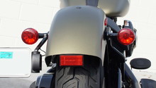
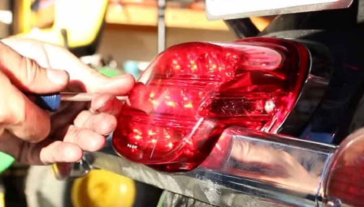
Step 1 – Remove the tail light
The tail light is mounted with two Phillips head screws. Remove these two screws and the tail light will come right off. Push in the sides of the clips and disconnect the wire harness.
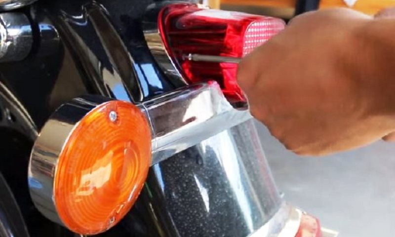
Figure 1. Remove the two Phillips head screws to remove the tail light. 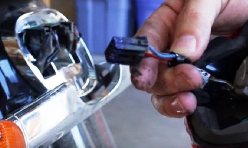
Figure 2. Disconnect the wiring harness.
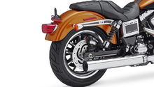
Step 2 – Unbolt turn signals
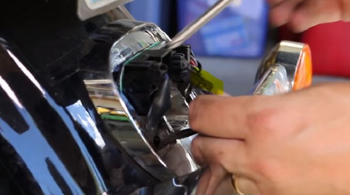
The turn signal bolts are a little tricky to get to, but not too difficult to remove. There are two 5/32" Allen head screws in the chrome piece they mount to below the tail light, often called the tree stem. One is situated above the other in the tree stem.
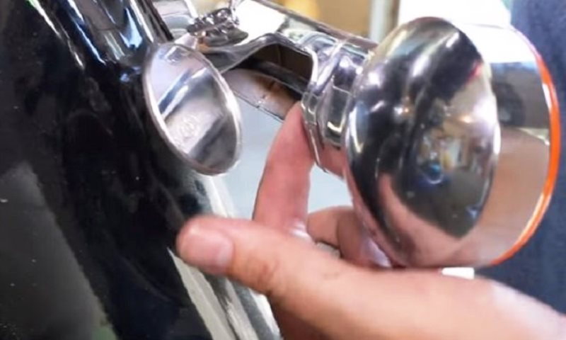
Figure 3. Remove the two 5/32" Allen head screws inside the tree stem. One is on top, the other is on the bottom. 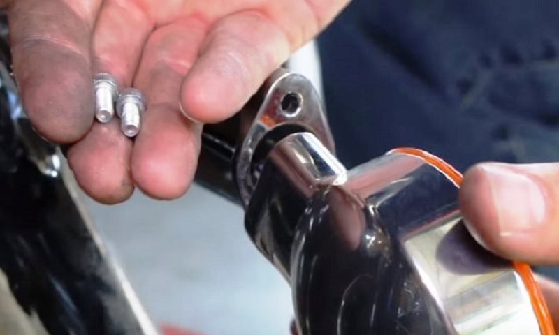
Figure 4. With both Allen bolts removed, the turn signal comes right off.
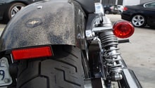
Step 3 – Disconnect the turn signal wiring harness
The wiring harness for the turn signals snake through the tree stem and up into the housing for the tail light. Unfortunately, the connector is too big to pull straight through the stem. You will need to snip the wires at the base of the connector to remove the connector and pull the wires out. Repeat these steps for both the right and the left side turn signals.
Pro Tip
Save the connectors and keep the wires in tact as much as possible in case you want to return the bike to stock, or resell them.
Step 4 – Install new LED turn signals
The turn signal wires for the new LEDs will likely not have a connector attached. If so, you'll have to cut it to run these wires through the stem and up to the connection point in the tail light housing.
- Mount the turn signals onto the stem with the two 5/32" Allen bolts first.
- Grab the smaller clips from the kit and insert the wires into the ports on the clip according to the instructions. Take your time here and make sure you insert the correct colored wires into the correct ports.
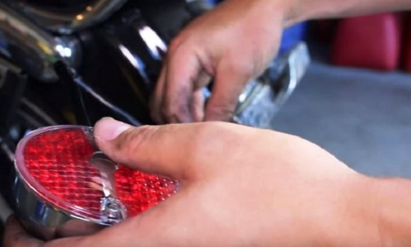
Figure 6. Run the LED wires through the stem and up into the tail light housing. 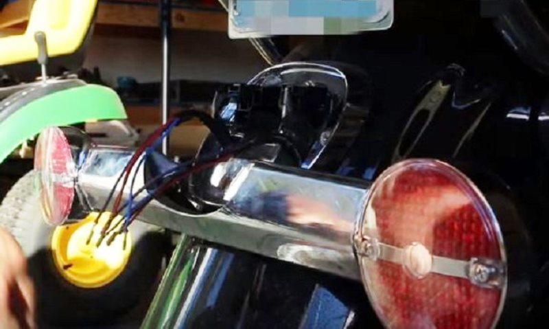
Figure 7. Mount the tails first with the original 5/32" Allen bolts. Save the wiring connectors for later.
- Each small connector has two ports, and each wire of the same color will go into the same connector.
- One connector will have the red and yellow striped wire, while one will have the blues.
- Your kit comes with two pigtail adapters that have a two-into-one configuration. Each pigtail clips into the two connections that you just made with the red and yellow, as well as the blue harness. Clip these two pigtails into the applicable harness.
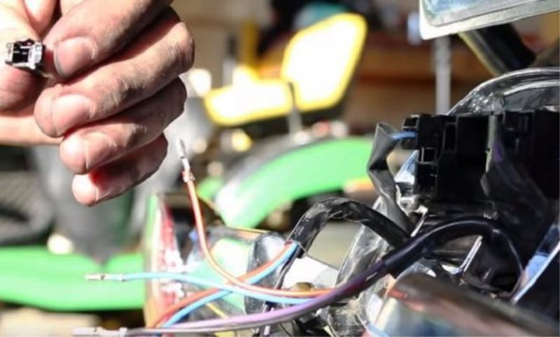
Figure 8. The turn signal kit should have come with the correct adapters. Follow the instructions carefully to match the correct wires to the ports. 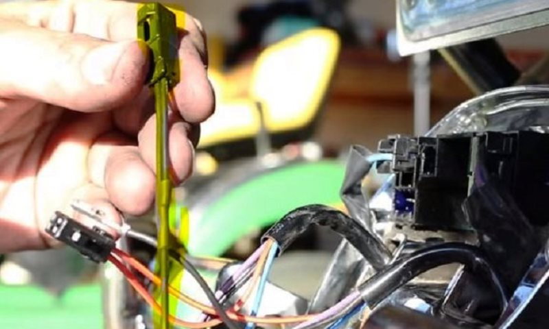
Figure 9. Your kit included two of these 2-1 pigtail harnesses that clip into the red and blue harnesses that you just attached.
- Your kit also includes two slightly larger connectors for the purple and black wires.
- These connectors have ports that are labeled "1" and "2." The purple wire goes into the number 1 port and the black in the number 2. These are the only wires that are crossed, meaning a black and a purple go into one connector. Follow the instructions carefully when making these connections.
- Plug the purple and black combo connectors into the right and left turn signal ports according to which side the turn signal you are working with is located. As the connectors are different sizes, they should only fit into the correct ports inside the tail light housing.
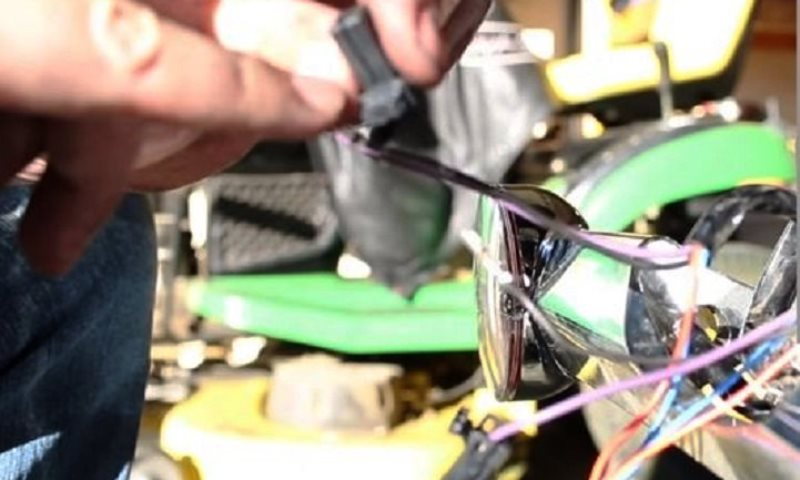
Figure 10. Make sure you find the port numbers and connect purple to 1 and black into 2. 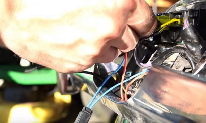
Figure 11. Plug the right turn signal into the right side port and the left turn signal into the left port.
Pro Tip
The wires fit into the connectors in only one correct position. If you don't hear and feel them click, flip it over and try again.
Step 5 – Connect tail light LED
Your kit comes with an LED adapter for the tail light, as well. This is a much larger connector than the turn signals. The wires from this adapter will plug into the adapter harness according to the color coding in the directions.
- The black wire from the LED adapter will go into the far right slot on the connector (number 4).
- The red and yellow wire from the LED adapter will go into the next slot on the connector (number 3).
- Skip the next two slots on the connector.
- The blue wire will clip into the slot number 1 on the supplied connector.
- Take the two blue connectors that you created from Step 4 and plug them into slot number 2 on the LED tail light adapter.
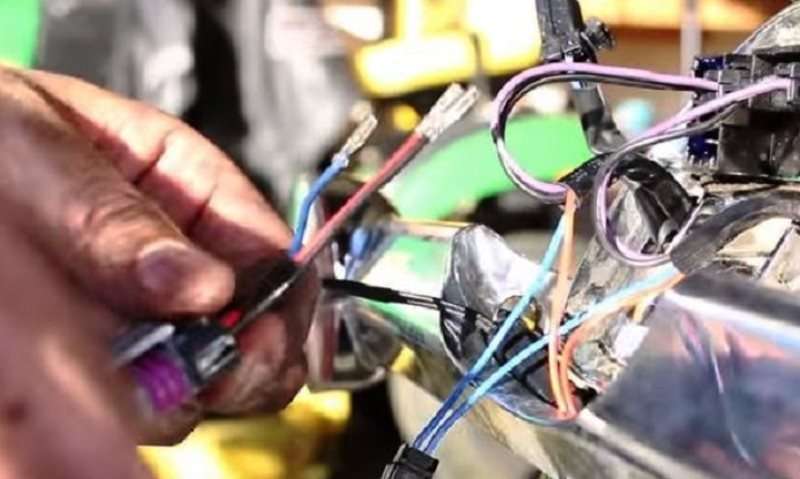
Figure 12. The tail light LED harness with the blue, black and red/yellow wires will clip into the supplied harness connector. 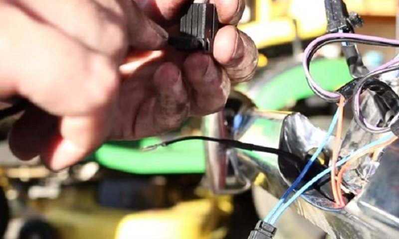
Figure 13. The LED tail harness wires plug into the supplied connector into slots 1, 3 and 4. Match the colors with the correct slot numbers. 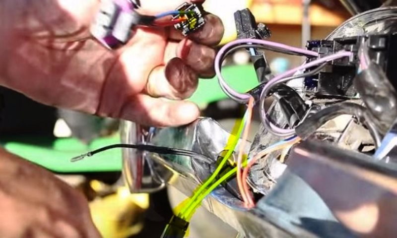
Figure 14. The two into one blue wire you created in Step 4 plugs into slot 2 on the LED tail light wiring adapter.
- Pull the fender tip lamp wiring harness out of its top left slot in the tail light housing
- The red/yellow "Y" or 2 into 1 connection you made in Step 4 will clip into slot 2 (the only open one on this connector).
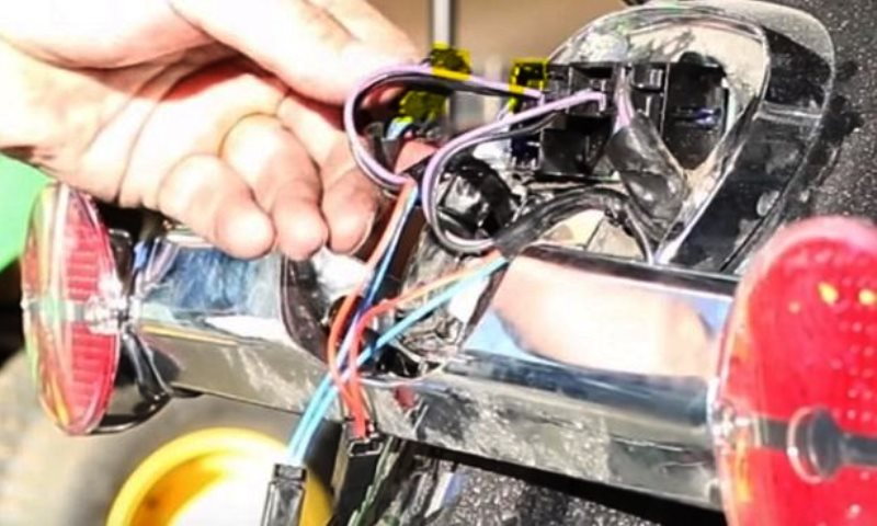
Figure 15. Disconnect the fender tip harness and plug your red/yellow wiring you created in Step 4 into slot 2. 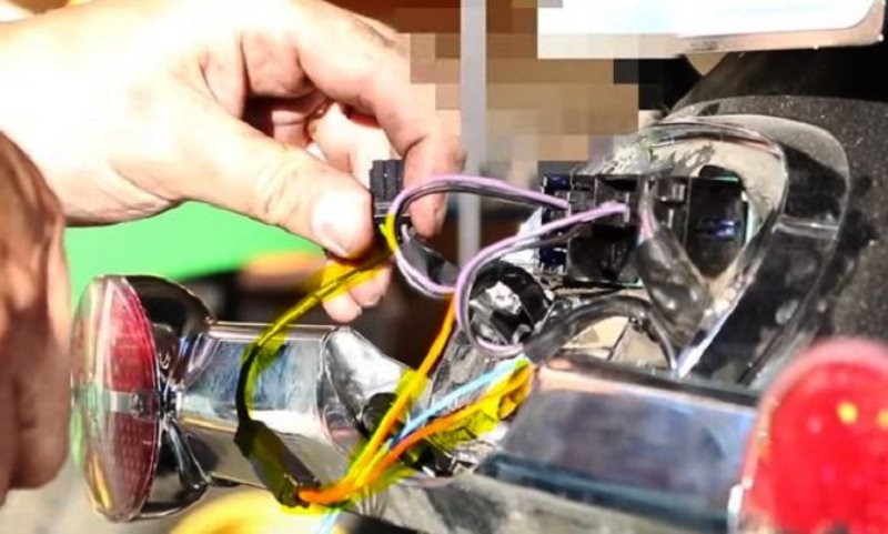
Figure 16. Insert the yellow-red wire from Step 4 into slot 2 of the fender tip harness and plug the harness back into the port in the housing.
Pro Tip
If your model does not have the fender tip lamp, the kit will come with an adapter to plug your yellow-red wires into it (slot 2 as well), and then plug it into the open slot in the housing where the fender tip lamp would plug into if your model had that option.
Step 6 – Mount new LED tail light and test your work
Tuck all the wires into the housing as neatly as possible and connect the LED harness to the back of the new tail light. Secure the new tail light with the two Phillips head screws. Turn on your bike and make sure the tail light is working, hit the brakes and the turn signals and make sure that they are working appropriately. If you have any issues, double check your wiring instructions and make any necessary corrections.
Featured Video: Brake Lights and Turn Signals Installation
Related Discussions
- LED Lights - HDForums.com
- LED Taillight Bulbs - HDForums.com
- LED Tail Light Bulb - HDForums.com
- Rear Parking Lights/Blinkers - HDForums.com