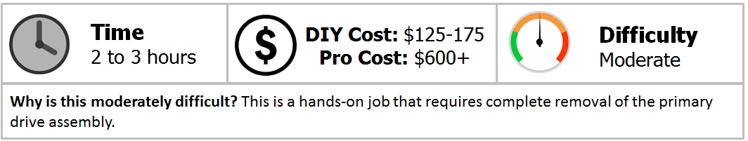
Harley Davidson Dyna Glide: How to Replace Drive Belt
The drive belt used on modern Harley motorcycles have a long service life without the need of any regular maintenance. That being said, at some point in a bike's life the belt will need to be replaced. The replacement procedure can be complicated and time consuming, but if you are familiar with turning wrenches, it isn't hard and you can enjoy a hefty savings versus taking it to the local dealer.
This article applies to Harley Davidson Dyna Glide models (2000-2016).
At first glance, the drive belt fitted to various Harley models may seem like an ordinary band of rubber. Despite this impression, loads of chemical and mechanical engineering went into the development of modern Harley drive belts to produce a truly astounding component. Compared to a contemporary drive chain, belts are much lighter weight, require no lubrication, resist stretching, and cannot rust or corrode. Harley drive belts are robust and have been known to last upwards of 100,000 miles before replacement becomes necessary. But that sort of mileage is a bit outside the norm, since Harley recommends a regular maintenance interval of 60,000 miles. It is best to regularly inspect the drive belt for damage or abnormal wear that would necessitate a replacement. Similarly, a bike that sees severe weather conditions, suffered an oil leak, or operates in a hot, dry, dirty environment may be apt for an earlier belt replacement interval. In any case, the following article will outline the procedure for replacing the drive belt on various Harley Davidson Dyna Glide models.
Materials Needed
- SAE wrench and socket sets
- Hex (Allen) key and Torx bit socket sets
- 1/4" and 3/8" drive ratchets and extensions
- 1/2" drive breaker bar
- Primary drive locking tool or wedge
- 1-1/2" and 1-3/16" sockets
- Large adjustable (crescent) wrench
- Torque wrench (in/lbs and ft/lbs)
- Impact gun (optional)
- Oil catch pan
- Shop rags
- Motorcycle jack
- Threadlocker (blue and red)
- Rubber mallet
- Screwdriver
- Chisel
- Pliers
Step 1 – Disconnect battery and drain primary
For safety purposes, disconnect the battery prior to disassembling the bike. Since this job requires removal of the starter, Harley recommends the battery and battery tray be removed from the bike completely.
- Remove the seat unit by undoing the screw at the back of it and lifting the seat from the bike.
- Remove the outer battery cover fastener (1) and pull the battery cover (2) away from the battery tray (3).
- Disconnect both battery cables, beginning with the negative (black) terminal.
- Remove the battery strap (6) and slide the battery from the battery tray.
- The battery tray is held in place with three fastening screws. Remove the screws and slide the battery cables through the tray as it is removed from the bike.
- With a catch pan handy, remove the primary drain bolt located at the rear of the primary cover and allow the oil to drain. Be sure to retrieve the sealing O-ring when removing the drain bolt.
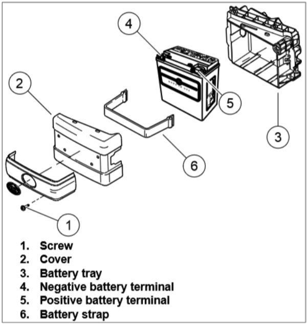
Figure 1. Battery and battery tray removal. 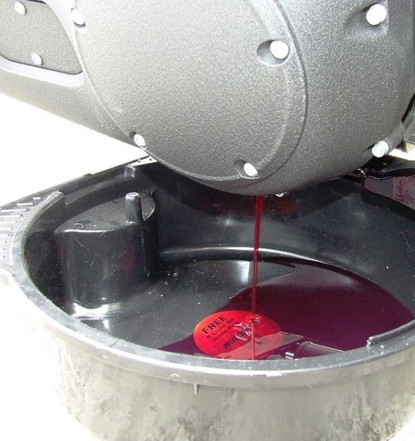
Figure 2. Draining oil from primary.
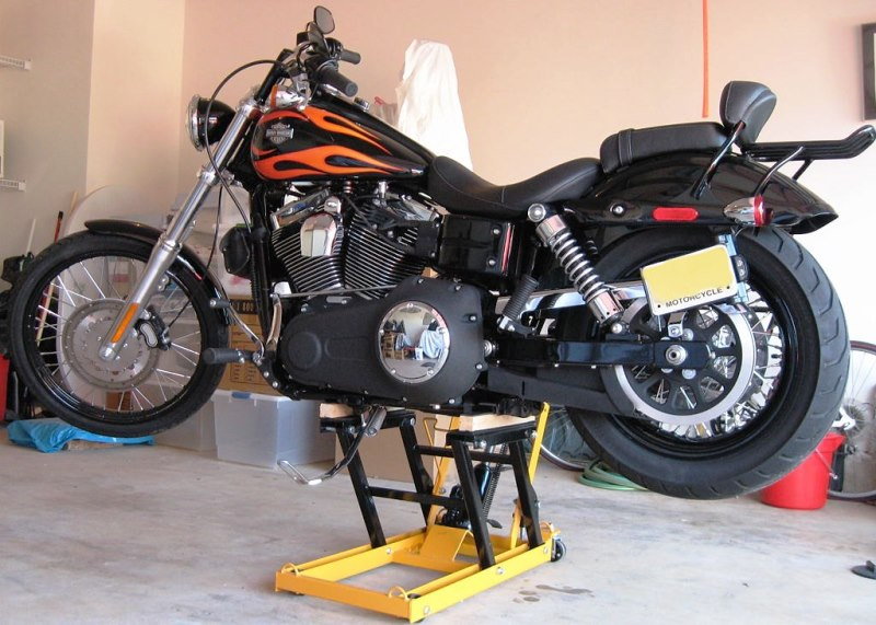
Step 2 – Lift and support motorcycle
After the oil had drained from the primary, lift and support the bike to make it easier to work on. Not only does this allow for easier access to the primary drive components, but will also allow for turning the rear wheel during drive belt replacement.
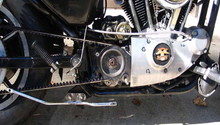
Step 3 – Remove primary drive assembly
With the bike supported, proceed with removing the primary drive assembly.
-
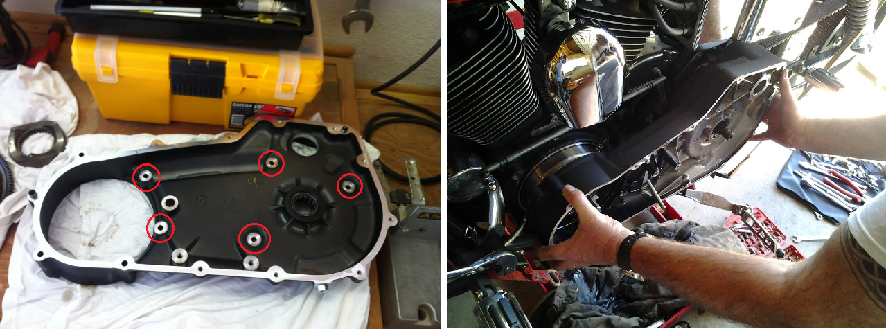
Remove the primary cover fasteners. Take note of each fasteners location, as two different lengths are used to hold the cover in place.
- With the fasteners removed, the primary cover can be separated from the primary housing. If it is stuck, a light tap with a rubber mallet can free it; a screwdriver or small pry bar can be used to separate the two.
- After the primary cover has been removed, proceed with removing the starter. For specific details on starter removal, see article How to Replace Starter.
- Remove the primary chain tensioner bolt(s) (2) and set the chain tensioner (1) aside.
- Using an 11/16" wrench and the appropriate size Allen wrench, loosen the clutch adjuster locknut (3). Remove the retaining ring/circlip (1) and finally the release plate (2).
- Be sure to grab the clutch pushrod, so it doesn't get lost if it slides out of the main shaft.
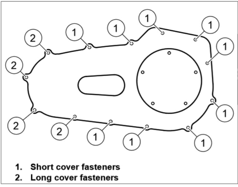
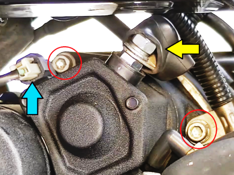
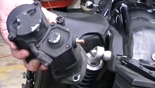
Figure 5. Starter mounting bolts (red) and electrical connections (arrows). 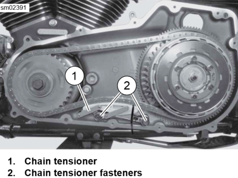
Figure 6. Primary chain tensioner assembly (2009 FXHD shown). 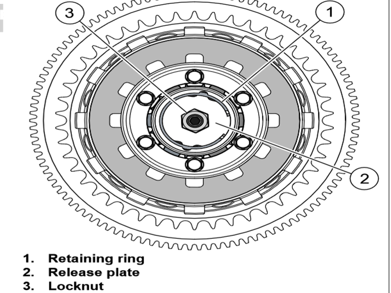
Figure 7. Clutch assembly.
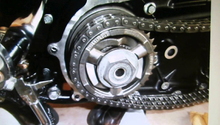
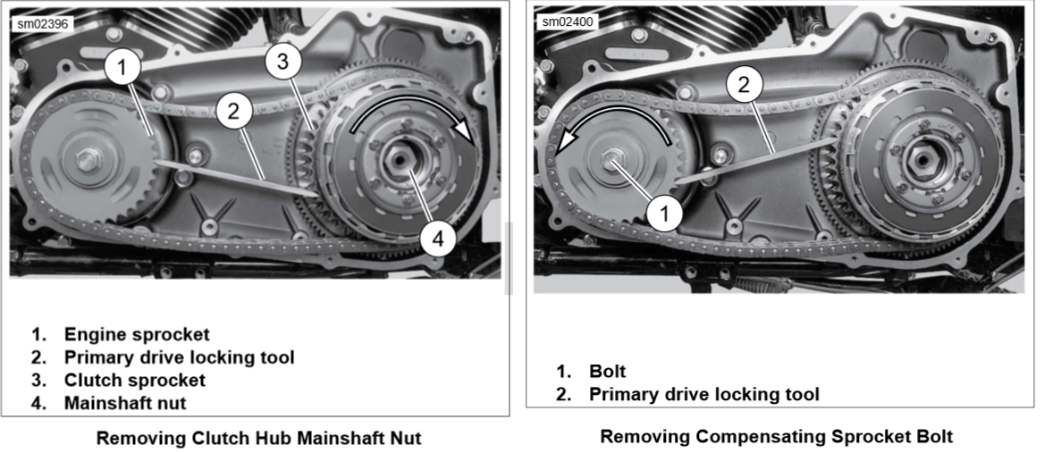
- Place a primary drive locking tool or similar wedge between the teeth of the compensating sprocket and clutch sprocket to prevent rotation when removing the compensating/crankshaft sprocket fasteners.
- Note that the clutch main shaft has reverse threads, but the compensating sprocket is threaded conventionally. The wedge will have to be flipped over after the clutch nut is removed to remove the compensating sprocket bolt. (See Figure 8.)
- With the primary drive locking tool or wedge in place, remove the main shaft nut in a clockwise direction using a breaker bar or impact gun.
- Next, flip your locking tool or wedge over and remove the compensating sprocket bolt (crankshaft bolt) in a counterclockwise direction. Collect the washer as the bolt is removed.
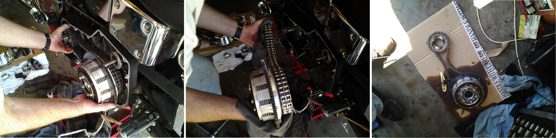
- The primary drive components can now be removed as a complete assembly and set aside. It is recommended that it be kept in a clean place that is free of dirt and debris.
- If applicable (typically bikes made in 2006 or earlier), remove the starter jakshaft spacer, noting its orientation.
- Remove the (5) fasteners securing the primary chain case housing in place and remove the housing from the engine. Older models may have lock-washers on each fastener that must first be bent open before the fasteners can be removed. As with the primary cover, a rubber mallet or screwdriver can help with removal if the housing is stuck in place.
Pro Tip
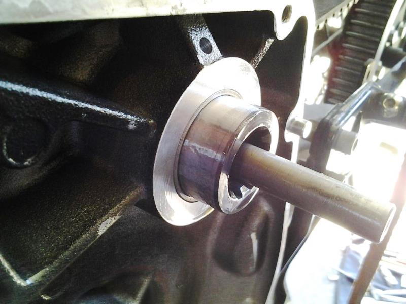
While the primary drive housing is removed, it is a good idea to inspect the main shaft seal as well as bearing and starter seal; replace them if necessary.
Step 4 – Replace drive belt
With the primary drive assembly out of the way, the drive belt is now accessible.
- Remove the front and rear fasteners on the upper belt guard and lift the belt guard from the swing arm. Similarly, remove the three fasteners securing the lower belt guard (debris deflector) and set the guard aside.
- Remove the axle retaining ring and loosen the rear axle. Loosen the axle adjusters on both sides of the swing arm and push the rear wheel forward to loosen the drive belt tension.
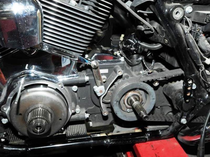
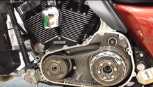
Figure 12. Side of engine with primary drive assembly removed. 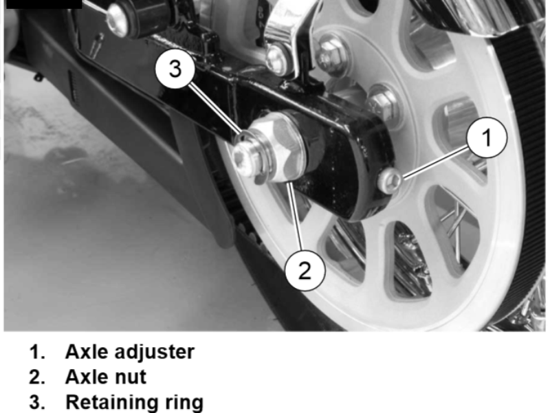
Figure 13. Axle and axle adjusters.
- Disconnect the left shock absorber from the swing arm mount and pivot the shock upwards.
- Remove the drive belt off of the front and rear sprockets. Discard the belt.
- Position your new belt onto the front and rear sprockets before re-attaching the shock absorber to the swing arm. Apply Threadlocker (blue) to the lower shock mount bolt before torquing to 30 to 40 ft/lbs.
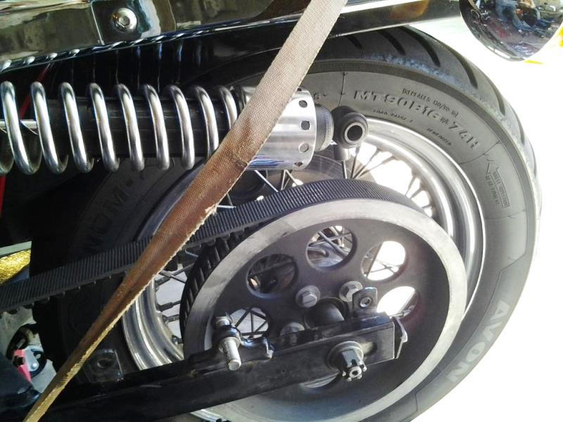
Figure 14. Shock disconnected and swung upwards for belt access. 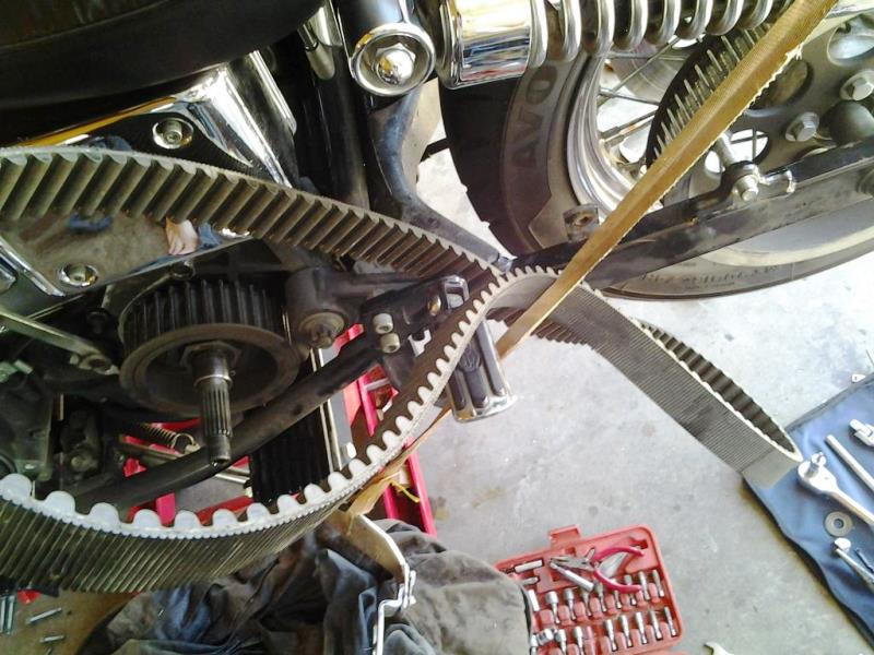
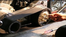
Figure 15. Belt removal. 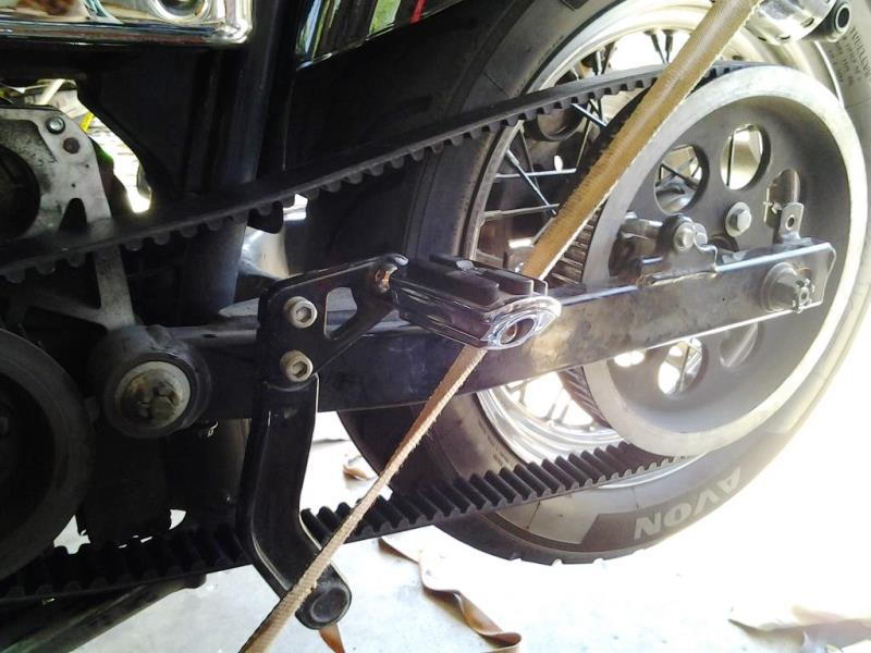
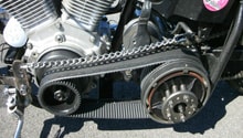
Figure 16. New drive belt in place.
Step 5 – Reassemble
Now that the new drive has been installed, the bike can be reassembled.
- Install the upper belt guard and tighten the fasteners. Ensure the spacers and washers are in he same order as when you took it off.
- Install the lower debris deflector.
- Place a piece of tape or plastic over the clutch hub main shaft splines to prevent damage to the oil seal when installing the primary housing.
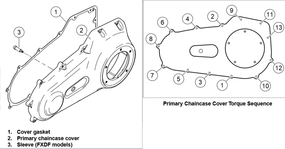
- Be sure that all gasket material has been removed and the mating surfaces are clean before installing the primary housing cover. Always use a new primary chain case housing gasket or O-ring, and new housing sealing fasteners.
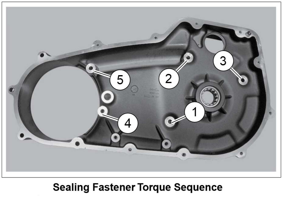
- Torque the (5) housing fasteners to 25 to 27 ft/lbs in the sequence shown below. If your model uses lock washers, bend the tabs flat against the head of each fastener.
- Slide the primary drive components (clutch assembly, primary chain, and compensating sprocket assembly) into position.
- Install the compensating sprocket bolt and washer hand-tight. Similarly, apply Threadlocker (red) to the clutch hub main shaft nut and install the nut hand-tight.
- Using a wedge or primary drive locking tool (as shown in Figure 8), tighten the compensating sprocket bolt in a clockwise direction to 100 ft/lbs to seat the sprocket.
- Loosen the bolt one full turn, then torque it to its final specification of 140 ft/lbs.
- Reverse the wedge or primary locking tool and tighten the clutch hub main shaft nut in a counterclockwise direction to 70 to 80 ft/lbs. Remove the wedge/locking tool.
- Install the clutch pushrod, release plate with lock-nut as well as adjusting screw, and retaining ring/circlip. The release plate should be stamped "OUT" to indicate its correct orientation. Be sure the retaining ring is fully seated in its groove.
- Install the primary chain tensioner.
- Install the starter jackshaft spacer (if applicable) and re-install the starter.
- Adjust the clutch as necessary, then tighten the clutch adjuster lock-nut while holding the adjusting screw with an Allen wrench.
- Make sure the primary housing cover mating surface is free of old gasket material before installing the cover and new sealing gasket.
- Install the short and long cover bolts in their corresponding holes before tightening the cover bolts to 108 to 120 in/lbs in the sequence shown below.
- Install the primary drain bolt and O-ring. Torque the drain bolt 14 to 21 ft/lbs before filling the primary with one liter of primary oil.
- Re-install the battery tray, battery, and battery cover.
- Re-install the seat unit.
Step 6 – Check belt tension
The final step in the drive belt replacement procedure is setting the correct belt tension.
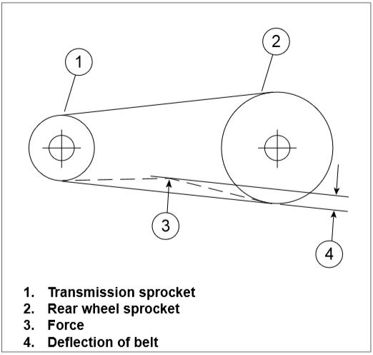
- Tighten up both axle adjusters equally to ensure proper wheel alignment and to achieve the correct belt tension. Harley suggests 5/16" to 3/8" belt deflection with the bike supported and the rear wheel in the air. Once proper belt tension has been set, tighten the rear axle nut to 96 to 105 ft/lbs and the axle adjusters to 96 to 120 in/lbs. With the axle and axle adjusters tight, double check the belt tension once more before installing the axle retaining ring.
Featured Video: Drive Belt Replacement
Related Discussions
- Changing Drive Belt on Dyna - HDForums.com
- 2007 Street Bob Drive Belt Replacement - HDForums.com
- Clutch Cable Adjustment? - HDForums.com