When you click on links to various merchants on this site and make a purchase, this can result in this site earning a commission. Affiliate programs and affiliations include, but are not limited to, the eBay Partner Network.
Hey all. I'm looking for insight on how to wire this three terminal starter relay on my 65 FLH. Can anyone advise the wiring schematics or supply a diagram? Thanks yall!
You're awesome man, thank you. I'm just making those connections dorectly? Am i disconnecting anything off the current wiring? I know, Im super amateur with the electric side of this rebuild but appreciate the help.
Standard convention would put pin 85 to ground, but it will work with 86 as ground (unless the relay is protected with a diode as some oem relays are).
It is #54 in the pic below (top right in pic) The diagram is from gthe HD service manual. It was standard on Electra Glides beginning 13 February, 1967. The factory kit was part #71451-65.
It was mounted to a bracket on the bottom of the battery carrier. I added one to my 65 back around 1986 and made my own bracket (the bracket was incorporated into battrey carriers until a different relay came into use around 1973). Never caused me a problem.
Last edited by panz4ever; Aug 20, 2022 at 02:15 AM.
Slideshow: Jason Momoa's latest restoration project blends 1920s Harley-Davidsons with modern electric technology, creating some of the most unusual hybrid motorcycles ever built.
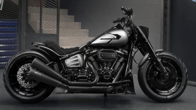
Harley-Davidson Fat Boy Becomes a Dark, Decepticon-Inspired Custom
Slideshow: Killer Custom's latest build relies on styling changes rather than performance upgrades, giving the cruiser an entirely different personality.
7 Surprising Harley-Davidson Products that Are Not Motorcycles
Slideshow: The bar-and-shield logo shows up on far more than motorcycles, some of the company's most unexpected products have nothing to do with riding.
Slideshow: From the troubled AMF years to modern misfires, these bikes earned reputations for reliability issues, questionable engineering, or disappointing performance.
Crazy Bunderbike Build Looks Amazing, But Is It Impossible to Ride?
Slideshow: The Swiss custom shop has taken a Harley Softail and stretched it into something so long and low that it looks closer to a rolling sculpture than a conventional motorcycle.