Harley Davidson Softail: Electrical Diagnostic Guide
Late model Softails use a complex network of computers to monitor the engine, transmission, and braking system. These systems must stay properly powered by the battery. The wiring connecting the systems together must remain intact. These problems occur and, although difficult to find at times, a series of test will help you narrow down the cause.
This article applies to the Harley Davidson Softail.
To start your Softail's engine and keep it running, there must be a constant supply of electricity going into and out of the battery. This electricity must be regulated; otherwise, heat will build and components will be quickly damaged. A multimeter is an invaluable tool when diagnosing electrical problems. When the right specifications are available to you, it's easy to take a reading at a component you suspect is faulty, and find out for certain whether it needs to be replaced or not. Diagnosing this way will save you hundreds, if not more, in unnecessary part replacement.

Materials Needed
- Multimeter
- Basic socket set (8mm-19mm)
- Ratchet
- Small ratchet extension
- Flat head screwdriver
- Amp clamp meter
- Electrical contact terminal cleaner
Step 1 – Check for trouble codes
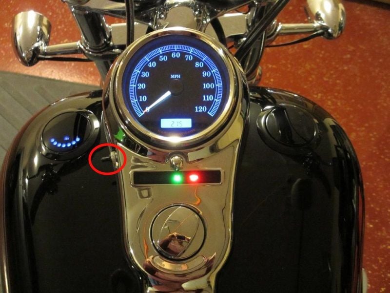
This method works for 2013 and earlier year models. Move your kill switch to the run position. Press and hold the black odometer reset button and turn the ignition switch to the ignition position. Hold the reset button until the message "DIAG" appears. Press and release the odometer button to access the module selection menu. The message "P55PtB" will appear. The letters and numbers stand for the different systems. Press and release the odometer button to move through the message characters. The first character "P" stands for PCM (powertrain control module). Press and hold the odometer button to access the PCM codes once the "P" is flashing. If a code is present, the code will display. Record the code number to research possible causes. Press and hold the odometer button to clear the code, and then shut off the ignition to exit the menu. Repeat the process to check the other systems.
For 2014 and later models, hold the odometer button down on the lift grip. Move the ignition switch to the ignition position. You'll see the "DIAG" message displaying. Release the odometer button and press it again to read the different codes at each module. The first module will be the ECM (engine control module). If you see a "N" displayed next to the module abbreviation, there are no codes present in that system. If you find a "Y" displayed next to a module abbreviation, hold down the odometer button to view the trouble code. To clear the code, press and hold the button until "CLEAR" displays, then press and hold the button again to erase it. Once you clear the code, a part number may display that correlates to the affected module. Press and release the odometer button again to move back to the module selection menu. Turn off the ignition to exit the module selection menu.
Some newer models are equipped with the "boom box." To access the codes on this system, leave the ignition off for 15 seconds. Press and hold the mute/power button, and then turn the ignition switch to accessories. Keep the mute button held as the system starts up and for three seconds after the warning screen appears. Press the accept option on the touchscreen, then select "DTC's." Any active codes will be displayed at this time.
A quick google search of your code should reveal most of the possible fault causes.
Step 2 – Check battery, charging system voltage, fuses and grounds
You'll need a voltmeter to perform this test. Use the related article How to Replace Battery to access the battery. Attach the positive voltmeter lead to the positive battery post and the negative to the negative. The battery should read above 12.2 volts.
If your Softail will start, keep the voltmeter connections in place and start the engine. The charging system should now be working and battery voltage should increase to above 14 volts.
If the battery reads low, try slow charging the battery for 12 hours and re-test. You can also take your battery to an auto parts store for a battery test. Most stores will test your battery for free.
Now would also be a good time to check fuses. Looking inside the fuse box, you'll see a 40 amp fuse. This is the main fuse protecting the circuit between battery positive and the starter motor. There should be 12 volts on both sides of this fuse with the ignition on. Touch the positive test lead to the fuse blade and the other to a good ground. 12 volts should display on your meter. If only one side displays 12 volts, the fuse is blown. If neither side displays 12 volts, there is a problem with the ignition switch or the wiring between the fuse and ignition switch.
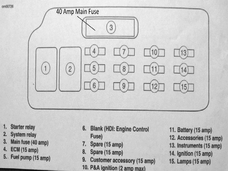
Figure 2. The fuse box diagram. 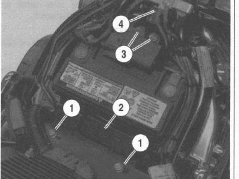
Figure 3. The fuse box is near the battery.
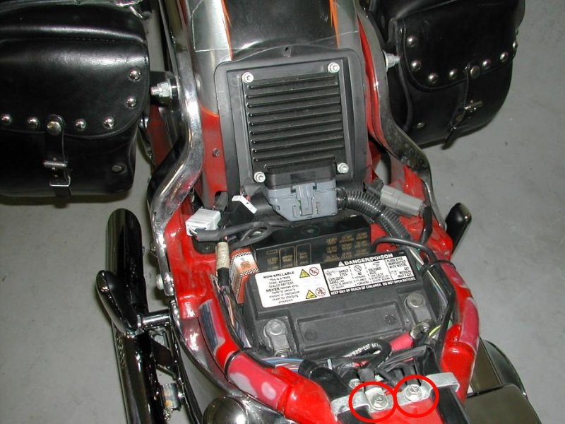
There are two main ground wires below the seat. These connections need to be clean and tight. In addition, there should be less than .2 volts between any ground wire and battery negative with the ignition on. More voltage indicates high resistance in the ground circuit.
If the battery continues to lose a charge after re-charging complete this step.
Step 3 – Check for a parasitic draw
A parasitic draw occurs when one or more circuit remains powered after the ignition is turned off. A draw on the battery of more than 0.02 amps can deplete the battery overnight enough to create a no start problem.
To test for a parasitic draw, place your multimeter to the amps setting in series with the battery. Do not turn your ignition on during this test. Remove the positive battery cable and attach one multimeter lead to the cable. Attach the other lead to the positive battery terminal. Read the current moving through the meter. If it's too high, unplug fuses one at a time until the draw disappears. The circuit where the fuse is located that eliminates the draw is either shorted or there is a problem with the system's module.
Step 4 – Check starter motor current draw
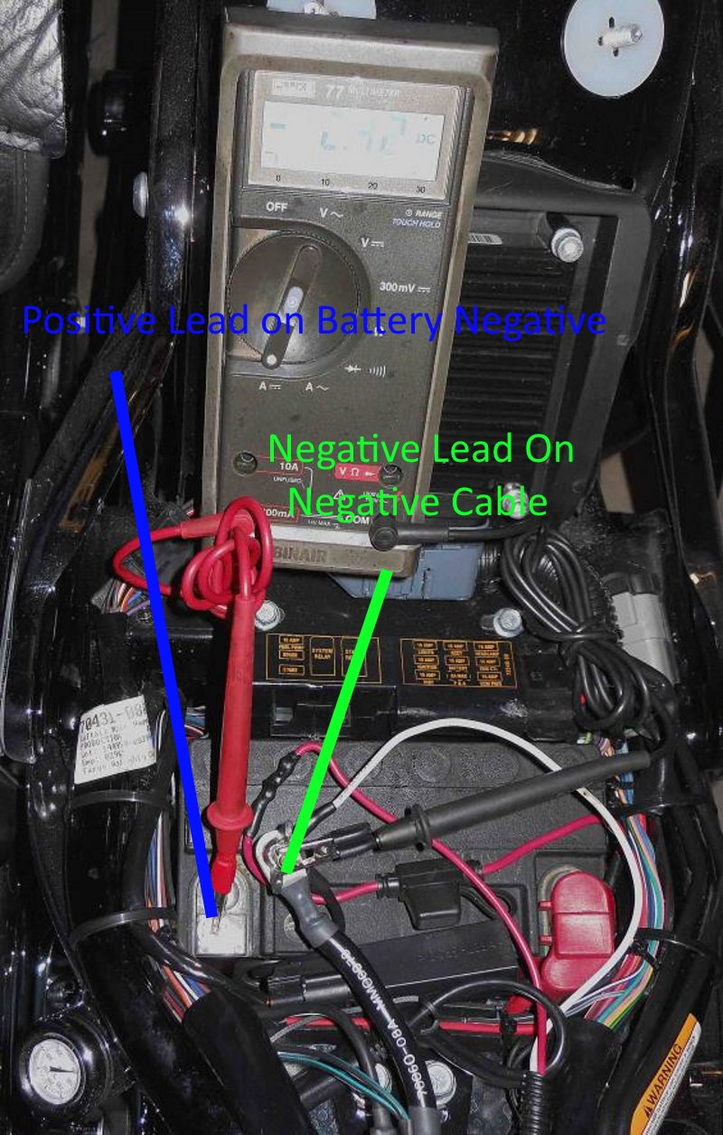
For this test you'll need an amp clamp. Place the amp clamp around the positive battery cable with the arrow on the amp clamp facing towards the starter. If your amp clamp has a max recording feature select it. Crank the engine for several seconds. Read the max reading on your clamp. A normal reading is around 100 amps. If your reading is higher, you may have mechanical engine damage, a faulty starter, or high resistance in the wiring routed between your starter and battery. The wiring can be checked fairly quickly. Place your multimeter's negative lead on the starter ground wire and the positive lead on battery negative. With the engine cranking, record the ground wires reading. A reading over .2 volts indicates the wiring has high resistance.
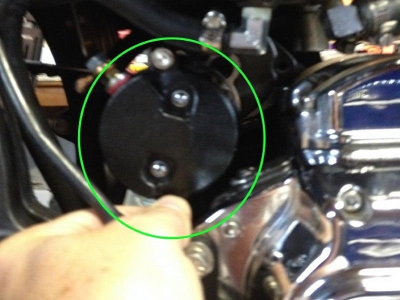
Figure 6. The starter on a early model Softail. 
Figure 7. This later year model has its starter below the seat near the battery.
Step 5 – Check voltage regulator and stator
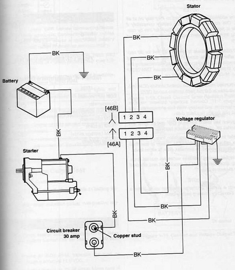
To check the voltage regualtor, locate the five wires connected to it. There are two paired wires (red and black) on one side, and three black wires on the other. The red wire is connected to the 40 amp fuse. The black wire connects to the main wiring harness ground near the battery. The other three black wires go to the stator. Make sure these wires are all clean and tight. Spray some electric terminal contact cleaner on the connections to promote conductivity.
To test the stator, you'll need a volt meter set to AC volts. Disconnect the voltage regulator and read the voltage between all five wires connected to the voltage regulator. Raise the engine rpm's to 2,000 and record the readings. All readings should be between 32 to 46 volts. If some of the connections are out of spec, you'll need a new stator. If the readings are low or zero, switch your meter to reads ohms, shut off the engine, and read the resistance between all five wires. A proper reading is around 0.2 ohms. The reading infinite or "OL" on your meter indicates an open circuit. The stator must be replaced. If the ohm meter test are good but the AC voltage test is bad, you'll need a new rotor. If you find both test resulted in good readings and the fuses as well as wiring has checked OK, the voltage regulator needs to be replaced.
Featured Video: Harley Diagnostic Trouble Code Assistance
Related Discussions
- Check Engine Light and Battery Light On - HDForums.com
- My Bike Won't Start After Sitting - HDForums.com
- Unidentified Starting Problem - HDForums.com
- Open Primary and Electrical Issues on 2013 - HDForums.com