Another hyper flash issue

Thread Starter
|
Intermediate
Joined: Jul 2017
Posts: 42
Likes: 5
From: Port Huron, MI
I recently relocated my front and rear turn signals with smaller bullet 12v LED lights. The front turn signals are only a two wire design so I lost my running lights. The running light wire in the meantime is just electrical taped off. I'm planning on installing resistors to correct the load on the turn signals.
But my question is with the load on the running lights which is none. Is it just a matter of running a resistor in line with the hot running light? One wire of the resistor going to ground and the other to the running light wire?
But my question is with the load on the running lights which is none. Is it just a matter of running a resistor in line with the hot running light? One wire of the resistor going to ground and the other to the running light wire?
Seasoned HDF Member


Joined: Aug 2008
Posts: 5,076
Likes: 1,008
remember, resistor do just as they say resist and that creates heat so be careful of where you install.
it might be a little while but i will post a jpeg of what you need and where to place it. no need for individual loads, this takes care of them all. i will have to retrieve it from photobucket and upload to imgur(thanks pb).
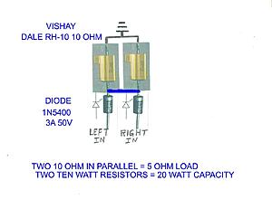

all you need to do is solder the input wire ends to the board so that they are stiff, you can insert them into the connector on the turns module.
Last edited by bustert; Sep 23, 2017 at 11:53 AM.
Thread Starter
|
Intermediate
Joined: Jul 2017
Posts: 42
Likes: 5
From: Port Huron, MI
That diagram is super helpful, thank you! This only makes the bike think there's running lights installed, correct?
would this setup be sorta the same thing as the Custom Dynamics Load Equalizer?
would this setup be sorta the same thing as the Custom Dynamics Load Equalizer?
remember, resistor do just as they say resist and that creates heat so be careful of where you install.
it might be a little while but i will post a jpeg of what you need and where to place it. no need for individual loads, this takes care of them all. i will have to retrieve it from photobucket and upload to imgur(thanks pb).


all you need to do is solder the input wire ends to the board so that they are stiff, you can insert them into the connector on the turns module.
it might be a little while but i will post a jpeg of what you need and where to place it. no need for individual loads, this takes care of them all. i will have to retrieve it from photobucket and upload to imgur(thanks pb).
all you need to do is solder the input wire ends to the board so that they are stiff, you can insert them into the connector on the turns module.
Seasoned HDF Member
Joined: Aug 2008
Posts: 5,076
Likes: 1,008
running lights do not need resistors unless of course the led does not have internal dropping resistors. the turns need the load, the new units do not as i understand it. the reason you put the input from the board into the connector hole that have the wires exiting out to the lamps on the module no need to feed the running.
Thread Starter
|
Intermediate
Joined: Jul 2017
Posts: 42
Likes: 5
From: Port Huron, MI
running lights do not need resistors unless of course the led does not have internal dropping resistors. the turns need the load, the new units do not as i understand it. the reason you put the input from the board into the connector hole that have the wires exiting out to the lamps on the module no need to feed the running.


Thread Starter
|
Intermediate
Joined: Jul 2017
Posts: 42
Likes: 5
From: Port Huron, MI
Installed the Custom Dynamics load equalizer and that corrected the issue. The red dash light also is no longer on. What an easy product to install. Just wanted to share what worked for me.

Thread
Thread Starter
Forum
Replies
Last Post
Voodoo
Ignition/Tuner/ECM/Fuel Injection
0
Nov 16, 2006 09:29 PM