When you click on links to various merchants on this site and make a purchase, this can result in this site earning a commission. Affiliate programs and affiliations include, but are not limited to, the eBay Partner Network.
Hi all, I got this 1976 ironhead XLCH with no wiring whatsoever. As of now I have a proper frame and motor A3XXXXH6 and a few other parts that will fit.
I decided to do the wiring myself, I'm an electronics technologist so this is not a big deal.
I may have a few questions when I'm further in my build but I will start with two and see where this thread evolves.
I have the generator (# 8 on the drawing) and the voltage regulator (#9 on the drawing). Which pin from the voltage regulator go to which pin of the generator.
Or more specifically on the schematics the pins are identified as B+, D+ and Df and on the connector they are 1,2 and 3. See top right corner of the schematic.
If anyone knows, something like this would help B+=1, D+=2 and Df=3. I may have figured it out, if the colors on the connector coming out of the voltage regulator match the drawing, I should be good.
I'll check when I get home.
I'm assuming here that the back plate of the voltage regulator is ground.
See attached pictures.
Also #15 on the schematic. which side of the ignition coil goes to 16. There are no markings on the Ignition Coil so I can't tell.
One side has a bigger screw than the other, that's it.
This is a project I'm working on with my 80+yo dad so I don't want to hear "you should buy a complete bike".
Last edited by purelife70; Jan 4, 2021 at 08:59 PM.
Hi all, I got this 1976 ironhead XLCH with no wiring whatsoever.
This is a project I'm working on with my 80+yo dad so I don't want to hear "you should buy a complete bike".
I will politely suggest that you will save time and money by purchasing a reproduction wiring harness from V-Twin
O.E. # 70001-76
V-Twin # 32-7614
J&P Cycle # 300-075
yes, it is easy to wire up, i had to do my 1974 ch. if the holes are there, run the main harness through the upper frame tube, hd used to do this but cheaped out and took the easy road. the wiring is 16ga.
on the coil, power into the left side when mounted and right to the points.
hd used two diff regulators and as you guessed it, has diff markings. now is the time to go electronic. i would have to pull some documentation to make for sure but do not have the time now, have to go to the farm.
it is a great project and i hope the best, these machines are an open canvas and with care can lasts decades, mine has nearly 200k miles.
I will politely suggest that you will save time and money by purchasing a reproduction wiring harness from V-Twin
O.E. # 70001-76
V-Twin # 32-7614
J&P Cycle # 300-075
Hi Again eighteight, thank you for the part numbers, I'll keep them in mind, but the idea here is to learn as much as possible while building the bike. So if/when it breaks down on the road I know the bike in and out and I can fix it if possible. I may not be "old hands" like some people here but I'm no city slicker either. :-)
on the rear strut mount in the center is a hole and on the steering neck, there is a hole where the harness exits to the terminal board under the visor for the head light. hd now tye-wraps them to the frame. coil mounts under the steering neck single hole, the bracket has two barrel spacers.
on the rear strut mount in the center is a hole and on the steering neck, there is a hole where the harness exits to the terminal board under the visor for the head light. hd now tye-wraps them to the frame. coil mounts under the steering neck single hole, the bracket has two barrel spacers.
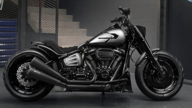
Harley-Davidson Fat Boy Becomes a Dark, Decepticon-Inspired Custom
Slideshow: Killer Custom's latest build relies on styling changes rather than performance upgrades, giving the cruiser an entirely different personality.
7 Surprising Harley-Davidson Products that Are Not Motorcycles
Slideshow: The bar-and-shield logo shows up on far more than motorcycles, some of the company's most unexpected products have nothing to do with riding.
Slideshow: From the troubled AMF years to modern misfires, these bikes earned reputations for reliability issues, questionable engineering, or disappointing performance.
Crazy Bunderbike Build Looks Amazing, But Is It Impossible to Ride?
Slideshow: The Swiss custom shop has taken a Harley Softail and stretched it into something so long and low that it looks closer to a rolling sculpture than a conventional motorcycle.
Engraved Rebellion: Inside Bundnerbike's Glam Rock II
Slideshow: A standard cruiser becomes an intricate metal canvas in the hands of a Swiss custom house known for pushing Harley-Davidson platforms far beyond their factory brief.