When you click on links to various merchants on this site and make a purchase, this can result in this site earning a commission. Affiliate programs and affiliations include, but are not limited to, the eBay Partner Network.
Disconnect all the wires from the coil terminal with the white wires on it. Are there only 2? Check for voltage on both wires (individually), ignition on, kill switch off. Both should have 0 volts. I suspect one will have +12V. Follow that wire back into the harness and find out where it goes. It is supposed to go up to the kill switch white wire, and I suspect it it going to the ignition switch. The other white wire and the blue wire go to your ignition module. You might want to make sure.
Anyway, one of those two white wires is picking up +12V somewhere it is not supposed to. Either the one that is supposed to go up to the kill switch, or the one that goes to the ignition module has a splice in it going to the switch. You'll just have to trace the wires.
Here's what I found, the junction at rear fender under the seat,book shows w into #4 then out #4. On the bike it's w into left #4 out #3 on top right. Witch should have orange but doesn't. Not sure what it means in book colored dots versus uncolored dots.ie there are eight dots for #3 ,five colored and three not. Close pic included here.
The empty #4 spot has a broke off wire connector down inside, can these two white wires simply just be unplugged and connected to each other? Isn't that the purpose of that junction anyway? Doesn't look like anything else joins those two.
I can't tell from your pic. Too blurry and not the whole schematic. The colored dots are there to help you trace a circuit, typically the ignition circuit.
Now, if the bike's wiring is not matching the schematic, I think you have found where the DPO struck. Problem being that they probably Aggie-rigged it for some reason instead of fixing whatever was wrong.
On the schematic: Follow the white wire from the kill switch. Does it go down to that #4 terminal? Follow the white wire from coil (the one not going to the ignition). Does it also go to the #4 terminal? Are there any other white wires on that terminal block?
On the bike: Put your volt meter on that #4 terminal and check it with the ignition on and with the kill switch on, and then off.
The empty #4 spot has a broke off wire connector down inside, can these two white wires simply just be unplugged and connected to each other? Isn't that the purpose of that junction anyway? Doesn't look like anything else joins those two.
We may have found the issue then. Trace out the schematic like I suggested above to make sure, and check for voltage at #4. It might be just as simple as moving the white wire from #3 to #4.
I can't reallt make out that schematic...But Makes no Diff.
The problem is the white wire plugged in where the orange wire is!
Do the turn signals work??
Orange is Hot from Keyswitch, controlling Turnsignals [among other things].
The White wire originates at the handlebar switch...specifically the [grey I think] wire is hot from Keyswitch to Kill Switch, white comes out of killswitch to Starter button, and to the Coil.
Is the #4 terminal power switched by the kill switch? Y/N? If Y, then the broken connection there is probably why the DPO moved it to the wrong terminal. As I said, "Problem being that they probably Aggie-rigged it for some reason instead of fixing whatever was wrong. "
Slideshow: Jason Momoa's latest restoration project blends 1920s Harley-Davidsons with modern electric technology, creating some of the most unusual hybrid motorcycles ever built.
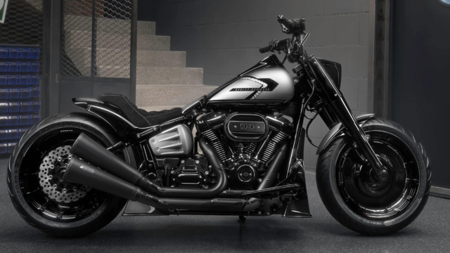
Harley-Davidson Fat Boy Becomes a Dark, Decepticon-Inspired Custom
Slideshow: Killer Custom's latest build relies on styling changes rather than performance upgrades, giving the cruiser an entirely different personality.
7 Surprising Harley-Davidson Products that Are Not Motorcycles
Slideshow: The bar-and-shield logo shows up on far more than motorcycles, some of the company's most unexpected products have nothing to do with riding.
Slideshow: From the troubled AMF years to modern misfires, these bikes earned reputations for reliability issues, questionable engineering, or disappointing performance.
Crazy Bunderbike Build Looks Amazing, But Is It Impossible to Ride?
Slideshow: The Swiss custom shop has taken a Harley Softail and stretched it into something so long and low that it looks closer to a rolling sculpture than a conventional motorcycle.