When you click on links to various merchants on this site and make a purchase, this can result in this site earning a commission. Affiliate programs and affiliations include, but are not limited to, the eBay Partner Network.
Dyna Glide ModelsSuper Glide, Super Glide Sport, Super Glide Custom, Dyna Glide Convertible, Super Glide T-Sport, Dyna Glide Police, Dyna Switchback, Low Rider, Street Bob, Fat Bob and Wide Glide.
ok im going to try to get this all done tonight. I am going to be posting my installation of the se 117 kit step by step. this is in no way a how to, just a thread to show others just how easy this install is. if I can do it, anyone can do it. you NEED a shop manual. you just have to have the specs, sequence, correct component position, etc. this is time consuming, but it is very doable for anyone mechanically inclined, with the necessary tools. I would greatly appreciate it if nobody responds until I finish posting all of the pictures, that way anyone who wants to use this as guidance doesn't have to sift through all the posts. thank you in advance.
First, I pulled the seat and battery. My order of doing things may not be identical as in the manual either by the way Remove the console, 3 Allen heads, top two have washers that are quite easy to loose. Disconnect the connectors and set aside I disconnected the wiring at the neck in front of the tank. Pain in the *** to remove all those wire harnesses but that's the way I did it
I didn't remove the air filter first as instructed because it wasn't blocking any fastners. Remove these 3 Allen heads and be careful not to tear the gasket cause I did not recieve a new one. These caps have o rings which also weren't supplied with the kit. They are a pain to remove, and I would suggest having touch up paint on hand, and wrapping a screw driver with electrical tape. They pry out. Next comes the exhaust. I loosened the bracket nuts to the pipe, and removed the bracket from the bike instead of the pipe. Loosened the clamp and wow, I've never had a pipe go on or come off so easy. Thank you D&D
Last edited by Nickd2689; Feb 7, 2017 at 08:15 PM.
I disconnected the front and rear o2 sensor connectors instead of removing them as it's easier. The front runs along the front under the voltage regulator. The rear goes under the seat. Have to be gentle with it but I slid the connector through the access hole towards the top on the left side of the compartment. Didn't have to pull the fuse box cover but the connector sticking up is the rear o2 connector. 2 1/2 nuts on each header, and the o2 sensor connectors, and the headers come out. Be sure to remove the old gaskets. Sometimes they can be stubborn. I used a flathead pocket screwdriver and gently pry around the inside instead of the outside, and mine came right out. The kit comes with tapered exhaust gaskets, I needed the flat screamin eagle gaskets for my exhaust. Next remove the backing plate for the air filter, 3 torx bits inside, and 2 hex heads above the throttlebody to the left and the right, these two thread into the heads. There are also 2 o rings behind these. I had one stick to the head until I removed the rocker box cover, then saw an oring fall and roll away. Luckily I hadn't removed the cover yet, so the engine hadn't been opened so it was easy to figure out where it came from.
This is a shot of the fuel gauge wiring. There is also a clip that holds it. I found it easiest to remove the front tank bolt, and loosen the rear, then remove the cross under tube under the front of the tank. I clamped the fuel line from the left side, then covered the right side with my finger. Next I lifted the front of the tank, and reinstalled the cross under tube above the frame, and let the tank rest on it. This elevated the tank just enough for me to see/remove the clip and gaugewIres
once disconnected, remove the rear fuel line, it is a quick connect, you shouldn't lose any fuel here. Then remove the rear tank bolt and out it goes. Next I removed the motor mount. Two 9/16 on the left side and one 9/16 on the right. On the right side the bolt goes through the frame, then a washer, then the motor mount, then a 9/16 nut. By the way, I used a wheel chock from harbor freight (normally don't trust their products, but the welds looked good and it was actually very secure) and a jack so I could place the bike in 6th and rotate the rear tire when I needed to rotate the crank, or valve train.
Last edited by Nickd2689; Feb 7, 2017 at 08:17 PM.
Remove the spark plug wires from the motor mount and it's ready to come out. At this point I disconnected every connector. Acr's, throttle body connector (the larger one on the left side of the throttle body has a push pin zip tie to secure the harness on the right side), fuel injector connectors, etc. the rear acr connector clips on to the wire loom on the left side of the upper frame, just above the engine, so remember to remove it before you try to remove the head. A shot of the bolt, and right side of the motor mount. I removed the coil pack/plug wires cause it's easy and it gave me more room. There's a electrical connector that plugs in behind the coil to a plastic holder, don't know what the connector is for, but it is not used. It doesn't have to be removed. Only 2 Allen heads secure the coil pack. I removed the plugs to make it easier to rotate the crank. Next I removed the covers, and the throttle body. Each cover has 6 fasteners, the left side of each cylinder are short, and the right side long. It does show where they go in the service manual. The throttle body and injectors/fuel line all come out together. 2 Allen heads on each side of the throttle body. I used a small Allen wrench on the left side of the motor, and an Allen key, with a long 1/4 in extension and ratchet for the right side. I removed the sensor on rhe throttle body first. One bolt and the sensor comes off the throttle body. When removing the t body just gentle pull the flanges back and lift the assembly up and back through the right side and it comes right out. Yes, I taped off the intake ports so nothing could fall in the engine that I was about to disassemble. A mechanics habit. Remove the oil breathers before the rocker arms, because if you mistakenly don't have it on the compression stroke, the pressure from the valve springs will be placed on the oil breather bolts, and they will break
I removed the pushrod cover clips, they just snap off with a flathead, then use paper clips and rubber bands to hold the covers up so I can feel the pushrods rotate to confirm there's no tension on them before removing rocker arms. 4 bolts for the rocker arms then they come out, and I also removed the pushrods at this point. Don't lose the 2 o rings. Two more o rings for the top of the pushrod covers under the bottom of each head. Next I removed the 6 bolts for the rocker box. I labeled front/rear for everything. Also, there is an o ring shown that fits in the rocker box for the oil breather. Replace EVERY o ring. Once disturbed they can not be trusted.
Last edited by Nickd2689; Feb 7, 2017 at 08:22 PM.
To remove the heads and cylinders, you will need a 12 point socket. Remove the 4 fasteners for each head. I followed the bolt removal sequence for everything I removed throughout this install. I suggest you do the same. Be sure to clean all gasket mounting surfaces with an sos pad. I didn't take pics of each surface I cleaned. Once you remove the head, the cylinder will slide off. There's an oring seal under the cylinder, and a smaller oring on each cylinder bottom that fits on to an opening on the crank case. Cover the cylinder studs with fuel line or shop rags so you don't damage them or your Pistons. Next I tore down the rear cylinder following the same steps as the front cylinder. Next remove the timing cover. You will lose oil even if you already drained the oil like I did. I removed the cam chain tensioner first. You don't have to worry about timing until you start assembling everything. For whatever reason this site isn't putting my pics in the order I select, so if any are off that will matter I will say when to do that particular step. Anyway the lifter covers come off with 4 Allen heads. Careful not to lose the anti rotation pin. The gasket has two prongs the cover it during installation. I removed the lifters with a magnet, but if you're replacing them feel free to use pliers. Another shot of the anti rotation pin. Do not forget to reinstall this. Since we're here, the lifter oil jets have to be positioned facing the passages in the crank case. The service manual will be more specific. From now on, service manual will be SM I stuffed clean shop rags in the crank case In case one of the piston c clips went flying. I removed one per piston using a flat pocket screwdriver, then pushed the wrist pin out from the opposite side. There is a tool in the SM for c clip removal. I've always used a flat screwdriver without struggling.
Last edited by Nickd2689; Feb 7, 2017 at 08:25 PM.
The rear cylinder stripped down. Piston wrist pin removal after removing one c clip. I also install one on each piston before installing it onto the rods. Easier to do them on a bench. Removing the rear cylinder lifter cover. I remove the lifter anti rotation pin with a magnet just to be safe. It will suck if you drop it in the crank case. So I'm sorta slow considering I pinned the HYDRAULIC tensioner before removal. I know I know. Anyway take the tensioner off first with two torx bolts. Use the cam locking tool, especially for assembly. It's a lot easier than having someone hold the rear brake. For timing components, better spend the extra 40 bucks. Clearly each sprocket has one bolt. The crank (bottom) is smaller and lower torque spec than the top (cam).
The 6 bolts with the blue marks around them have to come out to remove the cam plate assembly, the 4 with green marks are for the oil pump and don't have to be removed. Cam plate removed. 2 o rings seal it by fitting into the crank case, and a third gets placed on the back of the cam plate. Mine all stuck to the crank case and the mo co shorted me one. Never re use these o rings. It's not worth jeopardizing your lubrication system. It's important to note that not all o rings that are the same size are interchangeable. Should you be shorted one, it's important you know what the colors mean. The missing oring was brown, the original was black. luckily brown and black are "virtually interchangeable". A back shot of the cam plate. Two more Allen heads secure the tensioner. Remove these, then the snap ring on the front cam shaft. The snap ring is located on the front side of the plate, once removed, both cams, spacers, and chain will slide right out. I chose to reinstall the cam chains the facing the same way as they were before removal. A shot of the snap ring. Just pointing out this goes on the front (right) cam. I have the cam plate rotated here.
Last edited by Nickd2689; Feb 7, 2017 at 08:34 PM.
A shot of the cam chest. Be sure to check runout on your crankshaft with a dial indicator. I forgot to take a pic of mine so check the sm. The new cams have timing marks on the ends and the gears. Very nice. Slip em on the chain and line up the timing marks. Then install into the cam plate with spacers, and the snap ring. Check the SM for this as you have to check clearance of the snap ring ears with a feeler gage The cam bearing removal tool is amazing. So easy. Snap it into the bearing, slide on the sleeve and washer/bolt, and tighten. Remember, if you remove them improperly, they can break, and all those rollers end up in your crank case. The screamin eagle tool makes that impossible. This is the se cam bearing installer. I soaked the cam bearings in syn 3 first. The plate is held with fasteners that thread into the timing cover fastener bolt holes. When you install the bearings, the thicker side (side with the letters and numbers) is the side that the installer tool pressed against. So the thicker side of the bearings face outward once installed. Once the installer is set up, you torque it to 25 ft lbs, and the bearings are installed. I used a depth gage to double check. Use loctite (SM specifies red/blue) from here on out. Reinstall the six cam plate bolts using the proper torque spec and sequence. Before installing the cam plate, replace the three o rings I mentioned earlier. Install the cam gears without the chain, then place a straight edge against the sprockets, and try to insert the appropriate feeler gage in between the straight edge and the cam sprocket. Check SM for proper feeler gage. If you can fit it in between the two, you need to use a different cam spacer. The cam spacer kit isn't included in the 117 kit. When you measure this, set the timing marks so it's easier to install the gears when you get the chain on it. Next reinstall the sprockets and chain/tensioner. I found it easier to set the timing marks with the gears in the chain, and then install the locking tool, then install the gears to the cam plate. The locking tool only fits one way, and I highly suggest buying it.
7 Surprising Harley-Davidson Products that Are Not Motorcycles
Slideshow: The bar-and-shield logo shows up on far more than motorcycles, some of the company's most unexpected products have nothing to do with riding.
Slideshow: From the troubled AMF years to modern misfires, these bikes earned reputations for reliability issues, questionable engineering, or disappointing performance.
Crazy Bunderbike Build Looks Amazing, But Is It Impossible to Ride?
Slideshow: The Swiss custom shop has taken a Harley Softail and stretched it into something so long and low that it looks closer to a rolling sculpture than a conventional motorcycle.
Engraved Rebellion: Inside Bundnerbike's Glam Rock II
Slideshow: A standard cruiser becomes an intricate metal canvas in the hands of a Swiss custom house known for pushing Harley-Davidson platforms far beyond their factory brief.
Slideshow: Harley-Davidson's challenges aren't abstract; they show up in dropping shipments, shrinking dealer traffic, and strategic decisions that aren't yet translating into growth.




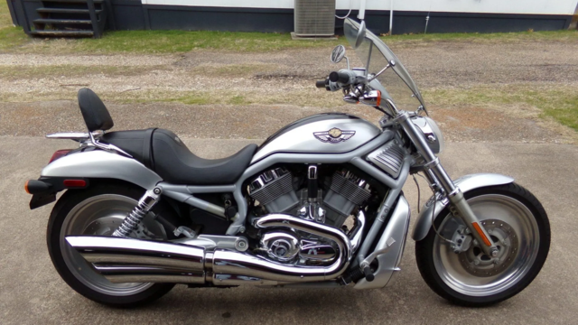

 my fxdls se 117 install step by step