




Thundermax ECM - any downsides (other than cost?)

Road Master


Joined: Sep 2008
Posts: 1,217
Likes: 48
From: WI

You could do that. But if you ride a HD with a proper tune, de-cat the head pipe, decent slip ons its like a new bike. Just sayin..

Road Warrior


Joined: Mar 2012
Posts: 1,522
Likes: 351
From: Holly Springs, North Carolina
Call Fuel Moto. Great advice, recommendations, sales & support.

Former Sponsor
Joined: May 2010
Posts: 555
Likes: 1
I couldn't be more happier with my ThunderMax tuner! Worth every cent imo. During the rally last year watched a bike get remapped and full dyno tune done on it. The numbers were printed then they removed the ECM and replaced it with the ThunderMax and road the bike a couple miles, put it on the dyno and did a couple pulls. Final result was the full dyno tune and remap was only 1/2% higher in HP and Torque. I'm a believer in the ThunderMax after seeing that.
Thank you,
Brian
Thank you,
Brian
Last edited by Samson_tech; Mar 27, 2014 at 08:40 AM.

Club Member
Joined: Sep 2010
Posts: 1,693
Likes: 461

Ok, in my opinion, if your not comfortable doing things yourself and digging into the finer points of how your auto tuner works, regardless of brand, then I suggest taking it to a dealer or Indy shop and have them tune it for you. I have a T Max on my 2012 Ultra and the base map was giving me some slight pinging under heavy load. I read all directions, read a lot on this and other forums and played around with the software to learn what it can do. I ended up retarding some timing out of the RPM range where the pinging occurred and solved the problem. I took out a little, then test rode it, then took out a little more until I was satisfied. Problem solved, I did it on my own with no extra cost and the bike runs great. Is it the best possible tune for competition racing? I doubt it but I'm happy with it and I have control of my tune. I think some people buy an auto tuner and expect it to always work perfectly without having to put any effort into learning the system, then become frustrated and think its a piece of crap. If your a do it your self person, then get a good quality auto tuner and have fun with it. If not, leave your tune up to a professional. JMO.

Road Master
Joined: Jan 2014
Posts: 763
Likes: 1
From: Calgary, Canada
For all that research you got just about everything wrong regarding the Power Vision. There's a 500 page PV thread in the tuning forum you might read sometime, start around page 300.
Just one example of several errors: You seem to insist it somehow piggybacks into the system, it does not. It connects directly to the ECM via the diagnostics port and completely replaces the stock map.
Just one example of several errors: You seem to insist it somehow piggybacks into the system, it does not. It connects directly to the ECM via the diagnostics port and completely replaces the stock map.
Go to their website and watch their videos. the second video show it connecting into the Auto tune Pro tuning module diag port and not the bike diag port.
There are two ways of using the PV
1. Directly on to the ECM/ECU
1a. If you do it this then you don't get the Wide band Sensors but only the Stock sensors. that is why it is so cheap
2. Piggy back onto the Dyna Auto tune Pro kit which then connects to the ECM/ECU. This way you get to use the Wideband O2 Sensors and the Auto Tune pro kit.
Now I don't know exactly what the difference between the AutoTune Pro Kit (Advanced) vs Pro Vision Auto tune (Basic) but i'm sure the Kit does something more.
All though I have purchased the Thundermax Autotune ECM replacement I would change it in a heartbeat if I knew I wasn't wasting my time buying another thing which does the exact same.
Has there been any testing on the same bike by the two? e.g. A Dyna technician setup vs a Thundermax technician setup on the same bike. under the same conditions?
Is there a thesis or an unbiased report between the two?
I have not used the bike yet as it's in the bike builders for the engine work and painting.
Last edited by Fozzy4325; Mar 27, 2014 at 09:00 AM.
Road Master
Joined: Jan 2014
Posts: 763
Likes: 1
From: Calgary, Canada
You may need to do a bit more research. The manifold absolute pressure(map) sensors do the adjusting for pressure or elevation changes. The cylinder head temps are monitored along with the intake air sensors. The ecm makes adjustments for any changes as it has been programmed by the factory to do. The exhaust sensors have nothing to with those things.
What I am talking about is the following; TM, PV and Stock will us the MAP to adjust the injection. The O2 sensor will read a value of O2 coming from the burnt fuel and relay it to the ECM. It will analyze and give a value and create a an open + or open - or a closed value (Wideband only). When it registers too much or too little O2 in the exhaust the MAP will change the injection regulate.
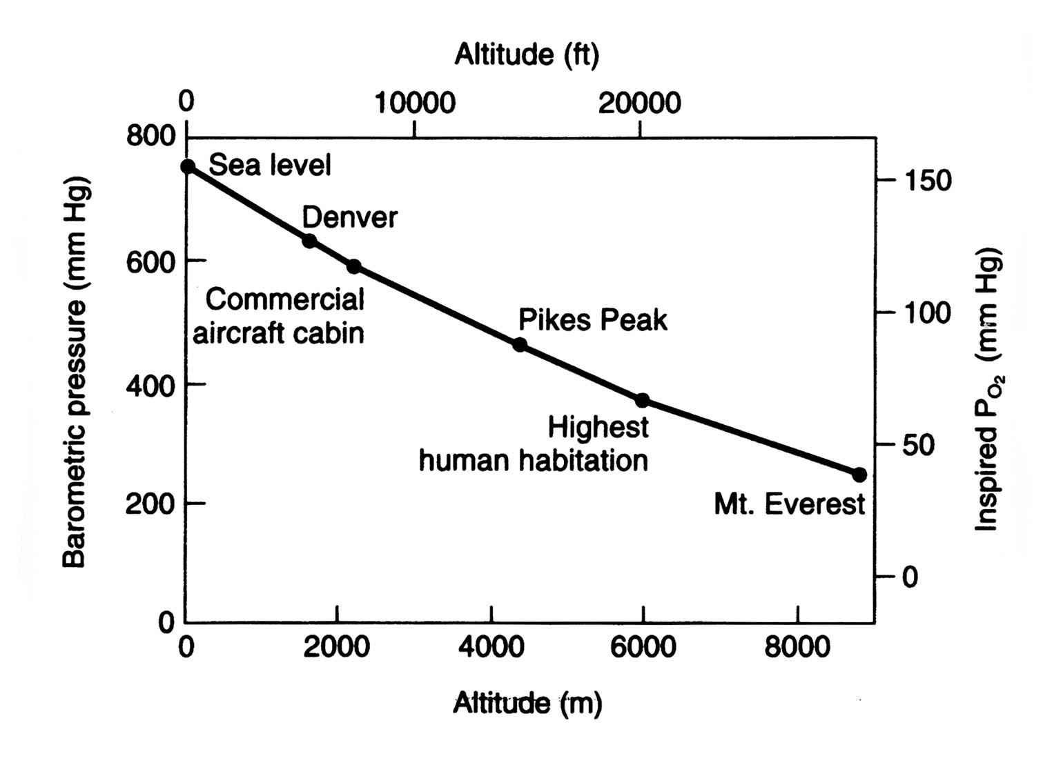
This is where the auto tuning can change a lot dependant on the barometric pressure changes in the same geographical area in different weather conditions or when traveling from the coast to the mountains.
The higher you go the less air is in the atmosphere meaning less fuel being used. Air Pressure vs Altitude.
So how do the O2 sensors work.
The Out of the Box PV uses Narrow band stock sensors connected to the ECM but it can use the wide band O2 sensors with the Auto Tune Pro kit for an approx extra $450 on top of the PVs approx $550
The Thundermax uses Wideband O2 sensors directly out of the box at a cost of approx $950
This description between Narrowband and Wideband sensors was taken from another post so I have copied and pasted it here.
First some fundamentals:
- The ECM uses oxygen sensors to ensure that the air/fuel ratio is correct for the catalytic converter/s, so that vehicle efficiency is maximized, and so that vehicle emissions are minimized. Based on the oxygen sensor signals, the ECM will adjust the amount of fuel injected into the intake system's air stream.
- The two most common styles of sensor are ... the "Narrow Range" or "Narrow Band" oxygen sensor, which is the oldest style, and which is simply called the "Oxygen Sensor" in the sense that this implies Narrow Range or Narrow Band ... the other style oxygen sensor is the "Wide Range" or "Wide Band" oxygen sensor, which is the newest style, and which is commonly called "Wide Range", "Wide Band" or even the "Air/Fuel RATIO" oxygen sensor.
- On OBDII (On Board Diagnostics II) vehicles such as the 80's after 95, two oxygen sensors (remember the implied thing of "Narrow Band" here) are required one of which is placed before the catalytic converter/s and one of which is placed after the catalytic converter/s. The oxygen sensor which is placed before the catalytic converter/s is used by the ECM to adjust the air/fuel ratio. This sensor in OBDII terms is referred to as "Sensor 1". On the other hand the oxygen sensor which is placed after the catalytic converter/s is used by the ECM primarily to determine catalytic converter efficiency. This sensor in OBDII terms is referred to as "Sensor 2."
- Old style oxygen sensors (implied "Narrow Band") are made of zirconia, with platinum electrodes and a heater element. The oxygen sensor generates a voltage signal based on the amount of oxygen in the exhaust compared to the amount of oxygen in the atmosphere. The zirconia element has one side exposed to the exhaust stream and the other side is exposed to the atmosphere. Each side of the zirconia element also has a platinum electrode attached. The platinum electrodes conduct the voltage generated. The way this works is when there is less oxygen in the exhaust, there is a large difference in oxygen content when compared to the amount of oxygen in the atmosphere. This in turn produces a higher voltage signal. On the other hand, when there is more oxygen in the exhaust, there is a small difference in oxygen content when compared to the amount of oxygen in the atmosphere. (Please note that this does not mean that there is more or less oxygen in the exhaust than in the atmosphere, it means it is comparing the delta of those two things, large delta = higher voltage signal ... low delta = lower voltage signal ... it is a comparative measurement).
Now, let's look at some actual signals as shown voltages...
With low exhaust oxygen content, we will have high oxygen sensor output which will show as something above .45volts which indicates a rich running condition.
With high exhaust oxygen content, we will have low oxygen sensor output which will show as something below .45 volts which indicates a lead running condition.
From the oxygen content, and the resulting signals, the ECM can determine if the air/fuel ratio is rich or lean and it adjusts the fuel mixture accordingly...
A rich mixture has less oxygen so the voltage signal is high in the range of .6 up to 1.0 volts.
A lean mixture has more oxygen so the voltage signal is low in the range of .4 down to .1 volts.
At the stoichiometric air/fuel ratio of 14.7:1, which is considered ideal for efficiency and emissions, oxygen sensor voltage output is approximately .45 volts which is right in the middle of lean or rich.
Because of the obviously limited range of the old style oxygen sensor ( .1 volt up to .9 volts or so ) the old style oxygen sensor is indeed unable to detect exactly how "lean" or how "rich" the air/fuel mixture is. So essentially the old style oxygen sensor acts as a relatively rapid switch and simply switches from lean to stoich to rich and back and forth and back and forth. This explains the oscillating effect of regular air/fuel gauges which are basically just showing the stoich switch effect.
Also because of the obviously limited range of the old style oxygen sensor, small changes in the air/fuel ratio from the set stoichiometric air/fuel ratio of 14.7:1 will really radically change the voltage signal of the oxygen sensor. Again, the oxygen sensor cannot detect the small subtle changes in the exhaust stream oxygen content produced by changes in the air/fuel mixture. Therefore, in the presence of these really radical changes in voltage signals, the ECM will continuously add and subtract fuel producing a lean/rich cycle that oscillates back and forth over and over.
- Now lets switch to the "Air/Fuel RATIO Sensor" (aka A/F Sensor) (implied "Wide Band"). The A/F Sensor voltage signal is relatively proportional to the exhaust oxygen content. In other words, it is not a comparative measurement between the basic deltas of amount of oxygen in the exhaust vs. amount of oxygen in the atmosphere as in the Narrow Band. Instead it is a signal that shows the proportions of oxygen in the exhaust. The A/F Sensor changes its current in relation to the amount of oxygen in the exhaust. A circuit then completes the translation, detects the direction and strength of the current flow, and puts out a voltage signal relatively proportional to the exhaust oxygen content.
Now let's look at some actual signals as shown voltages...
The A/F Sensor is designed so that at the stoichiometric set point of 14.7:1 there is absolutely no current flow and the resulting voltage signal put out by the circuit is 3.3 volts.
A rich mixture whcih leaves very little oxygen in the exhaust stream, produces a negative current flow and the circuit will produce a voltage signal below 3.3 volts.
A lean mixture which has more oxygen in the exhaust stream, produces a positive current flow and the circuit will produce a voltage signal above 3.3 volts.
It is important to really realize that with the A/F Sensor (Wide Band) the voltage signal IS proportional to the change in the air/fuel mixture. Think of the A/F Sensor as a generator capable of changing polarity. When the fuel mixture is rich (low oxygen content), the A/F Sensor generates current in the negative direction. As the fuel mixture gets lean (high oxygen content) the A/F Sensor generates current in the positive direction. And lastly when the exhaust is at the stoichiometric set point, there is no current generated.
There is a cool chart that I cannot connect to this thread but essentially we have a two axis chart that compares the A/F Sensor voltage signal to the A/F Ratio. Most A/F Sensors have an output of 1 to 4 volts. By eyeball, a 2.4 volt reading on the A/F Sensor equals a A/F Ratio of 12.0 which is really rich. Think of the amount of air to the amount of fuel with 12 parts air to one part fuel being rich. On the other hand a 4.0 volt reading on the A/F Sensor equals a A/F Ratio of almost 20 which is really really really lean. Again, think of 20 parts air to one part fuel being lean.
On our rigs, and with the A/F Sensor and A/F Gauge that I have here, we will typically see ratios somewhere between 10 (Really Rich) to 16 (Really Lean). In general when the rigs are running in "Closed Loop" the ratios are right around 14.7. Sometimes at idle and with hot weather, we will see Idle Ratios of 15.3 or 15.5 but I think that is still "Closed Loop Operation" (still some question about that though). Additionally, in general (at least with my rig) when the rigs are running in "Open Loop" the ratios adjust right away to approximately 12.6 (Rich) and then get richer and richer the longer you stay stuck to the pedal. I have seen ratios of 10.2 after really pushing the performance for a stretch.
So, as I have concluded in the other threads about Wide Band Oxygen Sensor Readings, it seems that on our rigs, which were all equipped with the old style oxygen sensors, the 14.7:1 "ideal" ratio for efficiency and emissions seems to stay impressively steady and indicates that the rig is in Closed Loop most of the time. However when the rig is in Open Loop, toyota clearly plays it pretty "safe" by having a really rich mixture. This leads to lots of other discussions but for the moment, and again at the request of several fine folks here, I'm trying to simply summarize the operation of our oxygen sensors (Narrow Band) as well as the operation of my A/F Sensor (Wide Band). I hope this helps.
- The ECM uses oxygen sensors to ensure that the air/fuel ratio is correct for the catalytic converter/s, so that vehicle efficiency is maximized, and so that vehicle emissions are minimized. Based on the oxygen sensor signals, the ECM will adjust the amount of fuel injected into the intake system's air stream.
- The two most common styles of sensor are ... the "Narrow Range" or "Narrow Band" oxygen sensor, which is the oldest style, and which is simply called the "Oxygen Sensor" in the sense that this implies Narrow Range or Narrow Band ... the other style oxygen sensor is the "Wide Range" or "Wide Band" oxygen sensor, which is the newest style, and which is commonly called "Wide Range", "Wide Band" or even the "Air/Fuel RATIO" oxygen sensor.
- On OBDII (On Board Diagnostics II) vehicles such as the 80's after 95, two oxygen sensors (remember the implied thing of "Narrow Band" here) are required one of which is placed before the catalytic converter/s and one of which is placed after the catalytic converter/s. The oxygen sensor which is placed before the catalytic converter/s is used by the ECM to adjust the air/fuel ratio. This sensor in OBDII terms is referred to as "Sensor 1". On the other hand the oxygen sensor which is placed after the catalytic converter/s is used by the ECM primarily to determine catalytic converter efficiency. This sensor in OBDII terms is referred to as "Sensor 2."
- Old style oxygen sensors (implied "Narrow Band") are made of zirconia, with platinum electrodes and a heater element. The oxygen sensor generates a voltage signal based on the amount of oxygen in the exhaust compared to the amount of oxygen in the atmosphere. The zirconia element has one side exposed to the exhaust stream and the other side is exposed to the atmosphere. Each side of the zirconia element also has a platinum electrode attached. The platinum electrodes conduct the voltage generated. The way this works is when there is less oxygen in the exhaust, there is a large difference in oxygen content when compared to the amount of oxygen in the atmosphere. This in turn produces a higher voltage signal. On the other hand, when there is more oxygen in the exhaust, there is a small difference in oxygen content when compared to the amount of oxygen in the atmosphere. (Please note that this does not mean that there is more or less oxygen in the exhaust than in the atmosphere, it means it is comparing the delta of those two things, large delta = higher voltage signal ... low delta = lower voltage signal ... it is a comparative measurement).
Now, let's look at some actual signals as shown voltages...
With low exhaust oxygen content, we will have high oxygen sensor output which will show as something above .45volts which indicates a rich running condition.
With high exhaust oxygen content, we will have low oxygen sensor output which will show as something below .45 volts which indicates a lead running condition.
From the oxygen content, and the resulting signals, the ECM can determine if the air/fuel ratio is rich or lean and it adjusts the fuel mixture accordingly...
A rich mixture has less oxygen so the voltage signal is high in the range of .6 up to 1.0 volts.
A lean mixture has more oxygen so the voltage signal is low in the range of .4 down to .1 volts.
At the stoichiometric air/fuel ratio of 14.7:1, which is considered ideal for efficiency and emissions, oxygen sensor voltage output is approximately .45 volts which is right in the middle of lean or rich.
Because of the obviously limited range of the old style oxygen sensor ( .1 volt up to .9 volts or so ) the old style oxygen sensor is indeed unable to detect exactly how "lean" or how "rich" the air/fuel mixture is. So essentially the old style oxygen sensor acts as a relatively rapid switch and simply switches from lean to stoich to rich and back and forth and back and forth. This explains the oscillating effect of regular air/fuel gauges which are basically just showing the stoich switch effect.
Also because of the obviously limited range of the old style oxygen sensor, small changes in the air/fuel ratio from the set stoichiometric air/fuel ratio of 14.7:1 will really radically change the voltage signal of the oxygen sensor. Again, the oxygen sensor cannot detect the small subtle changes in the exhaust stream oxygen content produced by changes in the air/fuel mixture. Therefore, in the presence of these really radical changes in voltage signals, the ECM will continuously add and subtract fuel producing a lean/rich cycle that oscillates back and forth over and over.
- Now lets switch to the "Air/Fuel RATIO Sensor" (aka A/F Sensor) (implied "Wide Band"). The A/F Sensor voltage signal is relatively proportional to the exhaust oxygen content. In other words, it is not a comparative measurement between the basic deltas of amount of oxygen in the exhaust vs. amount of oxygen in the atmosphere as in the Narrow Band. Instead it is a signal that shows the proportions of oxygen in the exhaust. The A/F Sensor changes its current in relation to the amount of oxygen in the exhaust. A circuit then completes the translation, detects the direction and strength of the current flow, and puts out a voltage signal relatively proportional to the exhaust oxygen content.
Now let's look at some actual signals as shown voltages...
The A/F Sensor is designed so that at the stoichiometric set point of 14.7:1 there is absolutely no current flow and the resulting voltage signal put out by the circuit is 3.3 volts.
A rich mixture whcih leaves very little oxygen in the exhaust stream, produces a negative current flow and the circuit will produce a voltage signal below 3.3 volts.
A lean mixture which has more oxygen in the exhaust stream, produces a positive current flow and the circuit will produce a voltage signal above 3.3 volts.
It is important to really realize that with the A/F Sensor (Wide Band) the voltage signal IS proportional to the change in the air/fuel mixture. Think of the A/F Sensor as a generator capable of changing polarity. When the fuel mixture is rich (low oxygen content), the A/F Sensor generates current in the negative direction. As the fuel mixture gets lean (high oxygen content) the A/F Sensor generates current in the positive direction. And lastly when the exhaust is at the stoichiometric set point, there is no current generated.
There is a cool chart that I cannot connect to this thread but essentially we have a two axis chart that compares the A/F Sensor voltage signal to the A/F Ratio. Most A/F Sensors have an output of 1 to 4 volts. By eyeball, a 2.4 volt reading on the A/F Sensor equals a A/F Ratio of 12.0 which is really rich. Think of the amount of air to the amount of fuel with 12 parts air to one part fuel being rich. On the other hand a 4.0 volt reading on the A/F Sensor equals a A/F Ratio of almost 20 which is really really really lean. Again, think of 20 parts air to one part fuel being lean.
On our rigs, and with the A/F Sensor and A/F Gauge that I have here, we will typically see ratios somewhere between 10 (Really Rich) to 16 (Really Lean). In general when the rigs are running in "Closed Loop" the ratios are right around 14.7. Sometimes at idle and with hot weather, we will see Idle Ratios of 15.3 or 15.5 but I think that is still "Closed Loop Operation" (still some question about that though). Additionally, in general (at least with my rig) when the rigs are running in "Open Loop" the ratios adjust right away to approximately 12.6 (Rich) and then get richer and richer the longer you stay stuck to the pedal. I have seen ratios of 10.2 after really pushing the performance for a stretch.
So, as I have concluded in the other threads about Wide Band Oxygen Sensor Readings, it seems that on our rigs, which were all equipped with the old style oxygen sensors, the 14.7:1 "ideal" ratio for efficiency and emissions seems to stay impressively steady and indicates that the rig is in Closed Loop most of the time. However when the rig is in Open Loop, toyota clearly plays it pretty "safe" by having a really rich mixture. This leads to lots of other discussions but for the moment, and again at the request of several fine folks here, I'm trying to simply summarize the operation of our oxygen sensors (Narrow Band) as well as the operation of my A/F Sensor (Wide Band). I hope this helps.
Last edited by Fozzy4325; Mar 27, 2014 at 09:47 AM.

Ultimate HDF Member
Joined: Jan 2008
Posts: 6,532
Likes: 132
From: SoCal
First of all the Power Vison reflashes the stock ecm just like a Sepst or a TTS. It does not replace the stock ecm. Some how I think you are a bit confused on how PV auto tune works. It does NOT tune while you ride. It collects data and then you can either accept the changes that PV suggests or ignore and then reflash if desired, the stock ecm with the attached PV. You can do the same thing with SEPST or TTS but you must use a computer to reflash. The wide band sensors just allow you to do this in a wider range of encountered AFR's. So regardless of NB or WB exhaust sensors being used the PV auto tune has no way of adjusting for elevation or temps. That is what the MAP, IAT and CH temp sensors do. Instant adjusting of afr's and ignition timing for conditions and loads encountered. The ecm adjusts as it is programmed for the info that is received from the sensors and the fuel and ignition are adjusted but the original fuel and ignition program is not changed. At least this is how is has been explained to me and my follow up research has confirmed this.
Last edited by qtrracer; Mar 27, 2014 at 10:15 AM.
You are correct if you are not using the Auto Tune pro kit. If you are using the auto tune pro kit you need to connect in to the diagnostic port of the tuner and not the ECM.
Now I don't know exactly what the difference between the AutoTune Pro Kit (Advanced) vs Pro Vision Auto tune (Basic) but i'm sure the Kit does something more.
All though I have purchased the Thundermax Autotune ECM replacement I would change it in a heartbeat if I knew I wasn't wasting my time buying another thing which does the exact same.
Has there been any testing on the same bike by the two? e.g. A Dyna technician setup vs a Thundermax technician setup on the same bike. under the same conditions?
Is there a thesis or an unbiased report between the two?
I have not used the bike yet as it's in the bike builders for the engine work and painting.
Now I don't know exactly what the difference between the AutoTune Pro Kit (Advanced) vs Pro Vision Auto tune (Basic) but i'm sure the Kit does something more.
All though I have purchased the Thundermax Autotune ECM replacement I would change it in a heartbeat if I knew I wasn't wasting my time buying another thing which does the exact same.
Has there been any testing on the same bike by the two? e.g. A Dyna technician setup vs a Thundermax technician setup on the same bike. under the same conditions?
Is there a thesis or an unbiased report between the two?
I have not used the bike yet as it's in the bike builders for the engine work and painting.
As for testing, I had a T-Max on my bike, replaced it with a PV and there was a noticeable improvement. This may be because between Fuelmoto & Dynajet there are a load of map to fit almost any situation. I always found the maps for the T-Max didn't fit my build. With the T-Max you do have to hook to a computer to accept tuning. I'm not saying T-Max is a bad unit, just that PV fit my needs better.
HD Forum Stories
The Best of Harley-Davidson for Lifelong Riders
7 Surprising Harley-Davidson Products that Are Not Motorcycles
Verdad Gallardo
8 Best Harley-Davidson Motorcycles Ever
Pouria Savadkouei
10 Worst Harley-Davidson Motorcycles Ever
Pouria Savadkouei
Killer Custom's Jail Break Is The Breakout That Refused to Blend In
Verdad Gallardo
Crazy Bunderbike Build Looks Amazing, But Is It Impossible to Ride?
Verdad Gallardo
Harley-Davidson Reveals Super Cool Cafe Racer Concept
Verdad Gallardo
Engraved Rebellion: Inside Bundnerbike's Glam Rock II
Verdad Gallardo
10 Motorcycles You Should Never Buy
Joe Kucinski
10 Things Harley-Davidson Needs to Fix in 2026
Verdad Gallardo
Club Member
Joined: Jan 2011
Posts: 937
Likes: 22
From: Ontario, Canada
Naw, just get in the band wagon it's more fun....😳. I installed a used thunder max on my 05 ultra and it was easy, and it woke it up, all in was about 450, and I can move it to the next bike or remove and re sell, only dis advantage is my local tuner "only does Power vision " but mine runs great with a canned map, and wide range sensors in true dual pipes
Road Master
Joined: Jan 2014
Posts: 763
Likes: 1
From: Calgary, Canada
You may need to do a bit more research. The manifold absolute pressure(map) sensors do the adjusting for pressure or elevation changes. The cylinder head temps are monitored along with the intake air sensors. The ecm makes adjustments for any changes as it has been programmed by the factory to do. The exhaust sensors have nothing to with those things.
Types of Power Vision tuning Installation

Thundermax Installation

Last edited by Fozzy4325; Mar 27, 2014 at 12:11 PM.