

Going to install some Handlebar Controls

Thread Starter
|
Cruiser

Joined: Apr 2014
Posts: 235
Likes: 76
From: Surrey, British Columbia . Canada
Hey guys
Need a little help here from the wiring guru�s . What I have is a 2004 Road King with a Reckless Fairing and a Sony CDX-H910UI, which has the remote in plug on the back. I want to install handlebar controls. I bought a set of Harley Davidson handlebar controls off Ebay and plan on taking the Audio control switches out of them and installing them into my control boxes and running the wires down through my bars. Once I have done that I will put a plug together to run the wires into my fairing. My fairing is quick release so the wires going in and out are on a plug system for easy removal.
I plan on using a ASWC-1 for the handle bar controls. I went to their web site and got their wiring diagram then printed up HD wiring diagram to trace the wires out.
So this is what I have figured out so far from the HD wiring diagram. The plug you are wiring the ASWC-1 to is the stock radio plug which I don�t have. I just have the wires running down from the Audio controls on the handlebars.
Connect the GN/OR wire from the ASWC-1 to pin 23. Pin 23 holds the GN/BE wire from the left hand control.
Connect the BK/GN wire from the ASWC-1 to pin 6. Pin 6 holds the BN/W wire from the right hand control.
Connect the W/GN wire from the ASWC-1 to pin 8. Pin 8 holds the BN/BK wire from the left hand control.
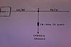
**Connect the GR/BE wire from the ASWC-1 to pin 3 and attach a 1k-ohm � watt resistor between this wire and Chassis ground. Pin 3 holds the PK/W wires coming from the right and left hand controls.
With a 1k-ohm � watt resistor, tie pin 5 of plug to Chassis ground. Pin 5 holds the V/BK wire coming from right hand control.
Connect pin 4 and pin 22 of plug to Chassis ground. Pin 4 holds the GR/W wire from the right hand control and pin 22 holds the GY/GN from the left hand control.
I just have a question on the ** one. I have attached photo, just what to make sure this is what they are asking you to do.
Thanks Bruce
Need a little help here from the wiring guru�s . What I have is a 2004 Road King with a Reckless Fairing and a Sony CDX-H910UI, which has the remote in plug on the back. I want to install handlebar controls. I bought a set of Harley Davidson handlebar controls off Ebay and plan on taking the Audio control switches out of them and installing them into my control boxes and running the wires down through my bars. Once I have done that I will put a plug together to run the wires into my fairing. My fairing is quick release so the wires going in and out are on a plug system for easy removal.
I plan on using a ASWC-1 for the handle bar controls. I went to their web site and got their wiring diagram then printed up HD wiring diagram to trace the wires out.
So this is what I have figured out so far from the HD wiring diagram. The plug you are wiring the ASWC-1 to is the stock radio plug which I don�t have. I just have the wires running down from the Audio controls on the handlebars.
Connect the GN/OR wire from the ASWC-1 to pin 23. Pin 23 holds the GN/BE wire from the left hand control.
Connect the BK/GN wire from the ASWC-1 to pin 6. Pin 6 holds the BN/W wire from the right hand control.
Connect the W/GN wire from the ASWC-1 to pin 8. Pin 8 holds the BN/BK wire from the left hand control.
**Connect the GR/BE wire from the ASWC-1 to pin 3 and attach a 1k-ohm � watt resistor between this wire and Chassis ground. Pin 3 holds the PK/W wires coming from the right and left hand controls.
With a 1k-ohm � watt resistor, tie pin 5 of plug to Chassis ground. Pin 5 holds the V/BK wire coming from right hand control.
Connect pin 4 and pin 22 of plug to Chassis ground. Pin 4 holds the GR/W wire from the right hand control and pin 22 holds the GY/GN from the left hand control.
I just have a question on the ** one. I have attached photo, just what to make sure this is what they are asking you to do.
Thanks Bruce


Stellar HDF Member


Joined: Feb 2016
Posts: 2,170
Likes: 188
From: Manitowoc county
well, my 2 cents worth is to go to Drag Specialties or your local HD store and buy the 23 pin plug and pins that would be found on a stock Classic of that same year
wire that plug as shown in a service manual, if memory serves correct i believe there are 2 or 3 pins that are powered. and key on and acc only and so forth,
if your head unit has rca outputs, you can leave out the 4 speaker wires as they wont be used
your handlebar switches from ebay will be color coded to proper pins in plug
at least this way, when you decide to change head units, yes when, not if, lol, cuz we all do, it will be a simple matter of unplugging your head unit adapter and pluggin in a new one
it may sound like a oain in the ****, but its very doable as i did this to my electraglide police that had no radio or hand controls
keep us posted and dont be afraid to ask
Thread Starter
|
Cruiser
Joined: Apr 2014
Posts: 235
Likes: 76
From: Surrey, British Columbia . Canada
My stereo system has already been wired in for a couple of seasons now. As of right now I am running two plugs into the fairing.
Because I was using 8-gauge wire from my positive and negative posts on the battery to my amp I used a two-pin Delphi connector for that. Then I used a 8 pin Deutsch DT series connector that holds my 4 rear speaker wires and key on and acc on wire for the head unit.
So I would be adding 4 more wires from the handle bar controls then the other three would just be going to chassis ground so not into the fairing and then one wire for the key on, acc on for the ASWC-1 and I may just ground the ASWC-1 to the amp ground. If that causes interference with the ASWC-1 I will just run another wire in for chassis ground.
So I really don’t need a 23-pin plug connector. I think I will swap out the 8 pin Deutsch for a 12 pin and I will be good to go.
Thanks
Bruce

Thread
Thread Starter
Forum
Replies
Last Post
02BlueDeuce
2014-2024 Touring Models
26
Dec 11, 2015 01:58 PM


