POWER DISSIPATION


Thread Starter
|
Stage II
Joined: Apr 2008
Posts: 2
Likes: 0
POWER DISSIPATION
Power dissipation has been empirically determined fortwo representative KEMET series: C052 and C062. Power dissipationcapability for various mounting configurations is shownin Table 3. This table was extracted from Engineering BulletinF-2013, which provides a more detailed treatment of this subject.
Note that no significant difference was detected betweenthe two sizes in spite of a 2 to 1 surface area ratio. Due to thematerials used in the construction of multilayer ceramic capacitors,the power dissipation capability does not depend greatlyon the surface area of the capacitor body, but rather on howwell heat is conducted out of the capacitor lead wires.
Consequently, this power dissipation capability is applicable to other leaded multilayer styles and sizes.

As shown in Table 3, the power dissipation capability ofthe capacitor is very sensitive to the details of its use environment.The temperature rise due to power dissipation should not exceed 20°C. Using that constraint, the maximum permissiblepower dissipation may be calculated from the data provided in Table 3.
It is often convenient to translate power dissipation capability into a permissible AC voltage rating. Assuming a sinusoidal wave form, the RMS “ripple voltage” may be calculated
from the following formula:
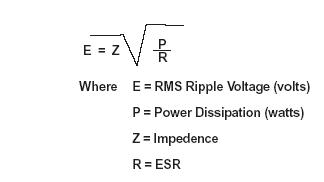
The data necessary to make this calculation is included in Engineering Bulletin F-2013. However, the following criteria must be observed:
1. The temperature rise due to power dissipation should be limited to 20°C.
2. The peak AC voltage plus the DC voltage must not exceed the maximum working voltage of the
capacitor.
Provided that these criteria are met, multilayer ceramic capacitors may be operated with AC voltage applied without need for DC bias.


Thread
Thread Starter
Forum
Replies
Last Post