When you click on links to various merchants on this site and make a purchase, this can result in this site earning a commission. Affiliate programs and affiliations include, but are not limited to, the eBay Partner Network.
Dyna Glide ModelsSuper Glide, Super Glide Sport, Super Glide Custom, Dyna Glide Convertible, Super Glide T-Sport, Dyna Glide Police, Dyna Switchback, Low Rider, Street Bob, Fat Bob and Wide Glide.
Before I get started I have looked around different threads and still have not gotten a definite answer. But I am a newbie and may have missed something.
So I am wiring the aforementioned driving lights to a 2016 wide
glide... and I also got the universal wiring harness from them
My problem is where in the world do I "T-tap" into to get a keyed/switched 12v power supply? Some people say not the high or low beam wire if you want to run them constantly. Others say not the blinkers because that inst a constant power when you signal. And then some say not the gauges because of frequency issues??
So what wire do I use then??
I want to run the lights with both my high and low beams.
EDIT: Sorry, just realized that it was not a touring bike with a fairing. Not sure if the plug I mentioned will be under your seat or not. The best net is to buy the Service Manual that has full wiring diagrams, or go ask your Harley service guys if they can show you where to hook up. Hopefully someone with knowledge of your specific model will show up to give you better information.
If you want to run them off the Accessory Switch that is on the fairing, there is a grey connector under the seat in front of the battery. It has four wires going to it. On my 2013 Electra Glide Classic, accessory switched power is the Orange/Red wire, and of course ground is the black wire. I believe the solid orange wire is ignition switched power, and the other wire is tied to the brake light.
The absolutely best way to do this is to buy the connector and pins at the Harley dealer and build a plug-in for the accessory connection so you aren't tapping or splicing wires. I did this for a laser fog light I installed so that I can control it using the accessory switch and it shuts off with the ignition. I did have to buy a special crimping tool for attaching the wire to the pins, but the installation looks clean and is completely reversible.
There are many ways to skin a cat...this is just my method. Let me know if you have any further questions. Good luck with your project.
I'll be putting the same on mine here in the next few months.
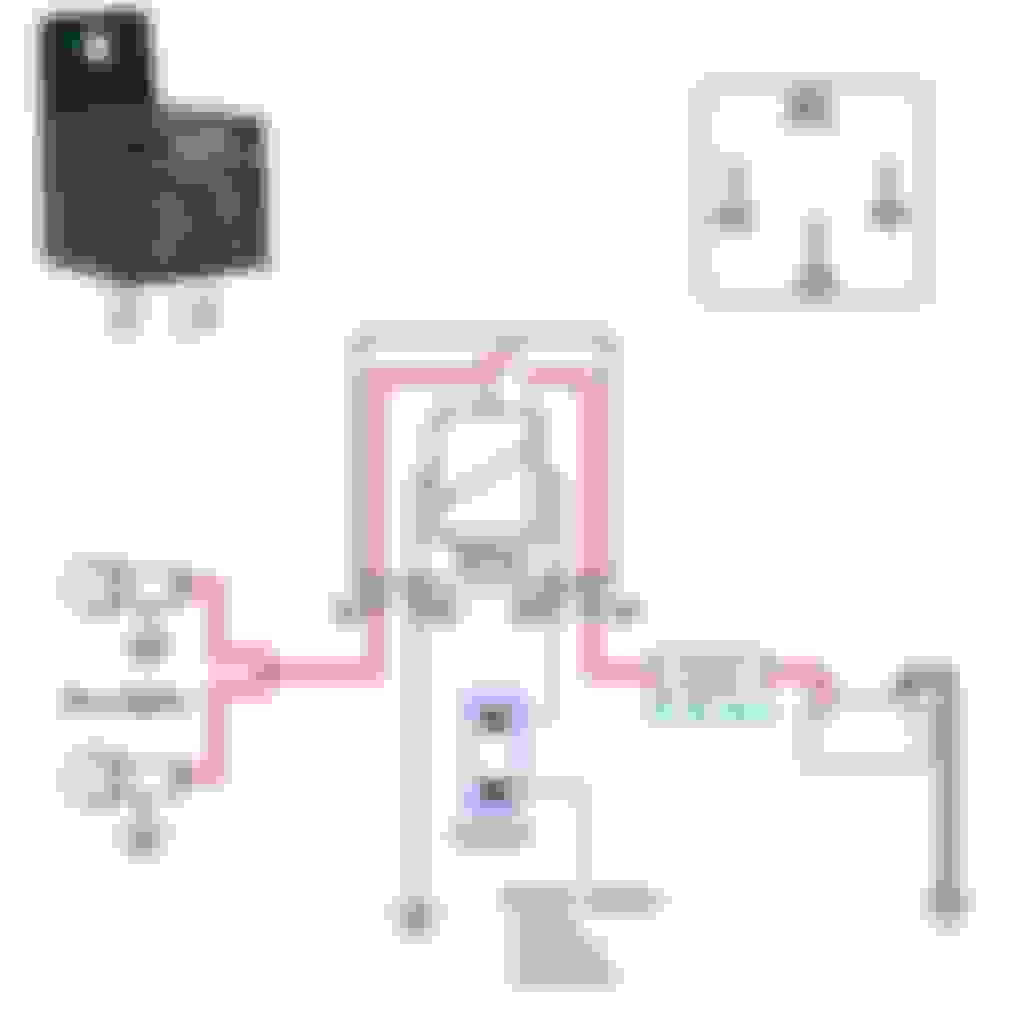
They pull 6 amps, so my thought is to run a supply wire from the battery, and then use a solid state relay to supply power to the lamps, with the control wire of the relay powered by a switched circuit... control wire would be low current, and could tie off the switched 'lights' line... or the switched main power off the main ignition.
86 = + (using a switch to activate relay) from:
- battery (best option for canbus bikes) or
- running lights (blue wire) or
- low beam (yellow wire) or
- high beam (white wire)
Here's a link to some Wire Gauge Tables which will help you to determine the awg wire size needed.
Last edited by FXD2003Rider; Apr 22, 2018 at 05:17 AM.
Seeing as to how the kit your getting has everything you need to wire the lights up and all you need is to locate a power source here is an idea. I don't know exactly what they have changed in the wiring with the newer models, so here is an idea. If you pull the headlight harness out of the neck and it is a traditional wire build up (ground wire, high beam wire and low beam wire, black, blue and yellow I believe) and not the newer data style then you might be in luck. Check the frame side of the harness, if it is like mine the four pug connecter will have an extra orange wire on the frame side and nothing on the light side. If you do have it, this orange wire is an accessory/switched power and you can pick up a pin to go into the light side of the connecter and you'll be set.
Last edited by blueangel73; Jan 21, 2016 at 06:41 AM.
The connector you're referring to is # 38A pin no 1 (as shown in this diagram centre/bottom) and is used in Intl models to feed the stationary front light bulb.
Canbus bikes have this connector as well however pin 1 color at the frame side is blue/black and not orange/white. This wire runs to pin L4 at the BCM (Front Running/Fog Light Power). This might be an option to get power to the pin 86 at the relay in my wiring diagram.
Originally Posted by blueangel73
Seeing as to how the kit your getting has everything you need to wire the lights up and all you need is to locate a power source here is an idea. I don't know exactly what they have changed in the wiring with the newer models, so here is an idea. If you pull the headlight harness out of the neck and it is a traditional wire build up (ground wire, high beam wire and low beam wire, black, blue and yellow I believe) and not the newer data style then you might be in luck. Check the frame side of the harness, if it is like mine the four pug connecter will have an extra orange wire on the frame side and nothing on the light side. If you do have it, this orange wire is an accessory/switched power and you can pick up a pin to go into the light side of the connecter and you'll be set.
The universal kit the OP plans to use is the pic below, so item #1 is the cable he could pin and place into the open socket in the housing I am referring to. (correct me if I am wrong FXD2003Rider). This will supply the 12v switched, correct?
That's correct, Mike. The 12 v power from the 4 pin connector 38A pin # 1 is switched by the ignition switch and also fused on the bike's fuseboard.
Funny to see that your picture shows what I drew in the diagram...
Originally Posted by blueangel73
The universal kit the OP plans to use is the pic below, so item #1 is the cable he could pin and place into the open socket in the housing I am referring to. (correct me if I am wrong FXD2003Rider). This will supply the 12v switched, correct?
7 Surprising Harley-Davidson Products that Are Not Motorcycles
Slideshow: The bar-and-shield logo shows up on far more than motorcycles, some of the company's most unexpected products have nothing to do with riding.
Slideshow: From the troubled AMF years to modern misfires, these bikes earned reputations for reliability issues, questionable engineering, or disappointing performance.
Crazy Bunderbike Build Looks Amazing, But Is It Impossible to Ride?
Slideshow: The Swiss custom shop has taken a Harley Softail and stretched it into something so long and low that it looks closer to a rolling sculpture than a conventional motorcycle.
Engraved Rebellion: Inside Bundnerbike's Glam Rock II
Slideshow: A standard cruiser becomes an intricate metal canvas in the hands of a Swiss custom house known for pushing Harley-Davidson platforms far beyond their factory brief.
Slideshow: Harley-Davidson's challenges aren't abstract; they show up in dropping shipments, shrinking dealer traffic, and strategic decisions that aren't yet translating into growth.