
Anyone install the passing lamp bypass kit?

Stellar HDF Member
Joined: Jan 2013
Posts: 2,721
Likes: 103
From: St. Louis, MO

Here is a nice how-to with pics on how to wire the the passing lights to the Aux circuit courtesy to Gordon, GTMalone who provides a cornucopia of tech articles on the Heritage Springer forum. The switch location is on the left side of the tank on a heritage springer vs the forks, but the concept is the same. You should check your wiring diagram to ensure your passing light switch is yellow and your aux is orange and white before proceeding.
This fix has the side benefit of allowing you to run a RTB controller making your rear turn signals work as brake lights. When I installed two different RTB controllers I kept blowing headlight/taillight fuses as at least on the heritage springer, the system is maxed at 15 watts with passing lights, headlight (low beam) and tail, when you add the turn signals the fuse blows. I think this is because the heritage springer comes with 35w bulbs in the passing lights that run as hot as can be (my reflectors are starting to melt a little).
This fix has the side benefit of allowing you to run a RTB controller making your rear turn signals work as brake lights. When I installed two different RTB controllers I kept blowing headlight/taillight fuses as at least on the heritage springer, the system is maxed at 15 watts with passing lights, headlight (low beam) and tail, when you add the turn signals the fuse blows. I think this is because the heritage springer comes with 35w bulbs in the passing lights that run as hot as can be (my reflectors are starting to melt a little).
Originally Posted by gtmalone
HSOA TECH TIPS
ELECTRICAL
DOCUMENT CHANGE HISTORY:
date ----- changed by ---------- recap of changes
--------------------------------------------------------------------------------------------------------------------------
6/11/2009 - gtmalone #2056 - document created
KEYWORDS AND KEY PHRASES
passing lamps - lighting - wiring - blown fuse -headlight - headlamp - fender lamp - front end - front fender removal
APPLICABLE YEAR/MODEL
1997-1999 Evo
2000-2003 TwinCam
1. TECHNICAL AREAS ADDRESSED
1.1 - Passing lamps increase load on lighting circuit close to maximum capacity resulting in occasional blown fuses. Moving power source for passing lamps from lighting circuit to aux circuit eliminates this problem. Also adds safety margin as passing lamps can be operated if the lighting circuit or headlamp fails for any reason.
1.2 - Gas tank must be removed or repositioned to access the fender lamp connector when removing the front fender. Relocating the connector to in front of the gas tank eliminates the need to remove or reposition gas tank.
Although the tasks are documented separately, both tasks can be done at the same time where you only have to remove/reinstall the gas tank one time.
2. HOW TO - PASSING LAMP REWIRE
2.1 - Remove or reposition the gas tank to access the wiring harness on the left side of the bike. Follow the steps in your service manual or methods you have used before.
2.2 - Locate and disconnect the passing lamp power connector which should be a single male/female spade connector separate from the main harness. The power source from the headlamp is yellow. The wire to the passing lamp switch is white. Refer to Figure 1.
2.3 - Locate the aux power circuit in the main harness on the left side of the bike. This should be an orange/white wire. Verify on your bike’s wiring diagram. Refer to Figure 1.
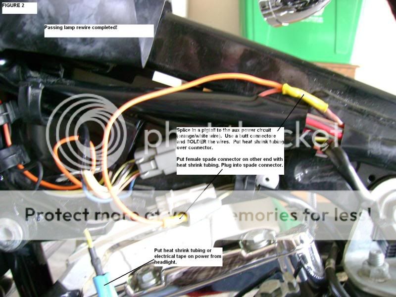
Refer to Figure 2 for the following steps.
2.4 - Cut a slit in the main harness sheath to expose more of the orange/white wire. Cut the orange/white wire where you have enough length on each end to work with.
2.5 - Strip approx ¼ inch of the insulation from both ends of the orange/white wire for soldering. Use a soldering iron to tin both ends of the wire.
2.6 - Slip a butt connector on the right-hand end of the wire. Crimp and solder the butt connector.
2.7 - Slip a piece of heat shrink tubing over the right-hand end of the wire. Push the tubing out of the way. Do NOT heat it yet.
2.8 - Cut a short length of wire that will be used to connect to the passing lamp connector. Strip and tin both ends of this wire.
2.9 - Solder a female spade connector on one end of this new wire. Place heat shrink tubing over the connector and heat to shrink.
2.10 - Insert the new wire and the remaining orange/white aux circuit wire into the butt connector from step 2.6. Crimp and solder the butt connector. Pull the heat shrink tubing from step 2.7 over the butt connector and heat to shrink.
2.11 - Place a piece of heat shrink tubing or electrical tape to completely cover the power connector from the headlamp.
2.11 - Plug the new wire you added into the passing lamp switch connector.
2.12 - Turn on the passing lamp switch. Turn the ignition switch to ON then AUX to verify the passing lamps are ON in both positions. Turn the ignition switch to OFF.
2.13 - Tuck the wiring out of the way. Use tie wraps as needed.
2.14 - Reinstall or reposition the gas tank.
ALL DONE!
3. HOW TO - FENDER LAMP CONNECTOR MOVE
Refer to Figure 1 for all steps.
3.1 - Remove or reposition the gas tank to access the wiring harness on the left side of the bike. Follow the steps in your service manual or methods you have used before.
3.2 - Locate and disconnect the fender lamp connector which should be a two pin AMP connector with orange/white and black wires. The orange/white wire runs to a second AMP connector attached to the main harness. Disconnect his connector.
3.3 - Remove the pins with the orange/white wire from both AMP connectors. Refer to the separate tech tip article on how to remove the pins.
3.4 - Remove the orange/wire from the AMP connector pins and replace with a longer length of wire. Pry the crimped section of the pins apart with a small jeweler’s screw driver or similar tool. Cut the wire from the pins. Strip approx 1/8 inch of the insulation from both ends of the orange/white wire for soldering. Use a soldering iron to tin both ends of the wire. Place the tinned end of the wire into the crimp section of each pin. Use needle nose pliers to recrimp the pins onto the new wire. Solder the wire to the pins. Reinsert the pins into the AMP connectors.
3.5 - Cut a 1 to 2 inch slit in the wiring sheath containing the black wire on the 2 pin AMP connector. Pull the black wire out of the sheath along this slit.
3.6 - Reconnect both AMP connectors.
3.7 - Turn the ignition switch to ON to verify the fender lamp is working.
3.8 - Tuck the fender lamp connector in next to the frame where it will be accessible with the gas tank in place.
3.9 - Reinstall or reposition the gas tank.
ALL DONE!
FIGURE 1

FIGURE 2
ELECTRICAL
DOCUMENT CHANGE HISTORY:
date ----- changed by ---------- recap of changes
--------------------------------------------------------------------------------------------------------------------------
6/11/2009 - gtmalone #2056 - document created
KEYWORDS AND KEY PHRASES
passing lamps - lighting - wiring - blown fuse -headlight - headlamp - fender lamp - front end - front fender removal
APPLICABLE YEAR/MODEL
1997-1999 Evo
2000-2003 TwinCam
1. TECHNICAL AREAS ADDRESSED
1.1 - Passing lamps increase load on lighting circuit close to maximum capacity resulting in occasional blown fuses. Moving power source for passing lamps from lighting circuit to aux circuit eliminates this problem. Also adds safety margin as passing lamps can be operated if the lighting circuit or headlamp fails for any reason.
1.2 - Gas tank must be removed or repositioned to access the fender lamp connector when removing the front fender. Relocating the connector to in front of the gas tank eliminates the need to remove or reposition gas tank.
Although the tasks are documented separately, both tasks can be done at the same time where you only have to remove/reinstall the gas tank one time.
2. HOW TO - PASSING LAMP REWIRE
2.1 - Remove or reposition the gas tank to access the wiring harness on the left side of the bike. Follow the steps in your service manual or methods you have used before.
2.2 - Locate and disconnect the passing lamp power connector which should be a single male/female spade connector separate from the main harness. The power source from the headlamp is yellow. The wire to the passing lamp switch is white. Refer to Figure 1.
2.3 - Locate the aux power circuit in the main harness on the left side of the bike. This should be an orange/white wire. Verify on your bike’s wiring diagram. Refer to Figure 1.
Refer to Figure 2 for the following steps.
2.4 - Cut a slit in the main harness sheath to expose more of the orange/white wire. Cut the orange/white wire where you have enough length on each end to work with.
2.5 - Strip approx ¼ inch of the insulation from both ends of the orange/white wire for soldering. Use a soldering iron to tin both ends of the wire.
2.6 - Slip a butt connector on the right-hand end of the wire. Crimp and solder the butt connector.
2.7 - Slip a piece of heat shrink tubing over the right-hand end of the wire. Push the tubing out of the way. Do NOT heat it yet.
2.8 - Cut a short length of wire that will be used to connect to the passing lamp connector. Strip and tin both ends of this wire.
2.9 - Solder a female spade connector on one end of this new wire. Place heat shrink tubing over the connector and heat to shrink.
2.10 - Insert the new wire and the remaining orange/white aux circuit wire into the butt connector from step 2.6. Crimp and solder the butt connector. Pull the heat shrink tubing from step 2.7 over the butt connector and heat to shrink.
2.11 - Place a piece of heat shrink tubing or electrical tape to completely cover the power connector from the headlamp.
2.11 - Plug the new wire you added into the passing lamp switch connector.
2.12 - Turn on the passing lamp switch. Turn the ignition switch to ON then AUX to verify the passing lamps are ON in both positions. Turn the ignition switch to OFF.
2.13 - Tuck the wiring out of the way. Use tie wraps as needed.
2.14 - Reinstall or reposition the gas tank.
ALL DONE!
3. HOW TO - FENDER LAMP CONNECTOR MOVE
Refer to Figure 1 for all steps.
3.1 - Remove or reposition the gas tank to access the wiring harness on the left side of the bike. Follow the steps in your service manual or methods you have used before.
3.2 - Locate and disconnect the fender lamp connector which should be a two pin AMP connector with orange/white and black wires. The orange/white wire runs to a second AMP connector attached to the main harness. Disconnect his connector.
3.3 - Remove the pins with the orange/white wire from both AMP connectors. Refer to the separate tech tip article on how to remove the pins.
3.4 - Remove the orange/wire from the AMP connector pins and replace with a longer length of wire. Pry the crimped section of the pins apart with a small jeweler’s screw driver or similar tool. Cut the wire from the pins. Strip approx 1/8 inch of the insulation from both ends of the orange/white wire for soldering. Use a soldering iron to tin both ends of the wire. Place the tinned end of the wire into the crimp section of each pin. Use needle nose pliers to recrimp the pins onto the new wire. Solder the wire to the pins. Reinsert the pins into the AMP connectors.
3.5 - Cut a 1 to 2 inch slit in the wiring sheath containing the black wire on the 2 pin AMP connector. Pull the black wire out of the sheath along this slit.
3.6 - Reconnect both AMP connectors.
3.7 - Turn the ignition switch to ON to verify the fender lamp is working.
3.8 - Tuck the fender lamp connector in next to the frame where it will be accessible with the gas tank in place.
3.9 - Reinstall or reposition the gas tank.
ALL DONE!
FIGURE 1
FIGURE 2
Last edited by Joe_G; Jul 14, 2014 at 08:51 AM.

Thread
Thread Starter
Forum
Replies
Last Post
Mordrapheus
Softail Models
10
Jul 29, 2016 07:03 AM