When you click on links to various merchants on this site and make a purchase, this can result in this site earning a commission. Affiliate programs and affiliations include, but are not limited to, the eBay Partner Network.
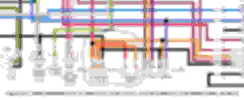
I know this is an old thread, but I'm trying to install some LEDs and wanted to use the switched accessory connector on my '09 Road King Classic. I've found the accessory connector and have a p/n for its mate (Deutsch DT06-4S). I want to hook up to both the BLK (ground) and ORG (ignition and nacelle switches in series). I tested voltage w/ ignition on and I'm seeing 7.63VDC, instead of ~12VDC on the GRN pin and I see no change in the ORG pin with ignition on and the nacelle in either position. Pin colors are based on the image below, but the actual colors are different for the '09 RKC (BLK, ORG, RED/YEL, ORG/RED)
Any idea as to why I'm measuring only 7.63VDC? In the wiring diagram above, I want to use Pin 3 (ORG, switched) and Pin 4 (BLK, Ground).
probably a dirty switch contact or bad[ish] ground...because you are installing LEDs which draw little current and will run on lower voltage I wouldn't worry about it too much...you can spray some wd40 or the like in the switch and flip it on/off a bunch of times to see if that helps, also measure ohms between grnd wire connection and actual ground of bike to see if issue is power side or ground side, and then trace back until you find weak connection ..
probably a dirty switch contact or bad[ish] ground...because you are installing LEDs which draw little current and will run on lower voltage I wouldn't worry about it too much...you can spray some wd40 or the like in the switch and flip it on/off a bunch of times to see if that helps, also measure ohms between grnd wire connection and actual ground of bike to see if issue is power side or ground side, and then trace back until you find weak connection ..
Well, if anyone's still following this thread or if someone runs into a similar issue... I found the problem. I'm not sure why I was getting 7.63V on the constant-hot (GRN wire), but after disassembling and testing everything within the nacelle, the reason why nothing else was working was because the previous owner must have pulled the fuse. The 15A P&A fuse was missing. I replaced it using the 15A spare and everything worked.
I bought some Deutsch DT06-4S connectors from Amazon (because the local Harley parts department couldn't be bothered with calling back after leaving a few messages) and wired the LED controller into the ORG and RED/WHT wires. Everything worked perfectly... the lights can be switched on or off at the toggle switch and they all light up red when I apply brakes.
Bottom line: If you're getting weird voltages at connectors, read the wiring diagram and check the fuse block to see if there's anything missing before you spend a couple/few hours tearing everything apart.
Slideshow: Jason Momoa's latest restoration project blends 1920s Harley-Davidsons with modern electric technology, creating some of the most unusual hybrid motorcycles ever built.
Harley-Davidson Fat Boy Becomes a Dark, Decepticon-Inspired Custom
Slideshow: Killer Custom's latest build relies on styling changes rather than performance upgrades, giving the cruiser an entirely different personality.
7 Surprising Harley-Davidson Products that Are Not Motorcycles
Slideshow: The bar-and-shield logo shows up on far more than motorcycles, some of the company's most unexpected products have nothing to do with riding.
Slideshow: From the troubled AMF years to modern misfires, these bikes earned reputations for reliability issues, questionable engineering, or disappointing performance.
Crazy Bunderbike Build Looks Amazing, But Is It Impossible to Ride?
Slideshow: The Swiss custom shop has taken a Harley Softail and stretched it into something so long and low that it looks closer to a rolling sculpture than a conventional motorcycle.