

Finding Tachometer Pulse Wire on Newer Can Bus Harleys


Thread Starter
|
Road Captain
Joined: Jun 2007
Posts: 632
Likes: 86
Okay, I have the problem solved when attaching aftermarket, non-Can Bus or non-plug-play tachs to late model bikes. You can obtain a tachometer pulse signal on any late-model H-D ( 2012+ Dyna & 2014+ Touring ) with the new Can Bus wiring system by simply tapping into one of the cylinder firing wires at the coil. You can no longer use the connector tap at the speedometer head as on prior models.
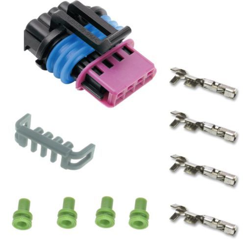
The coil on these models are basically a dual coil made into one with individual single firing to each cylinder. The coil assembly is attached with a 4-wire Delphi GT150 connector. There is a 12VDC power wire, an ION sensor wire, rear coil trigger, front coil trigger. The power wire is marked with a red stripe and on one end of the 4-wire row. I chose the front coil trigger wire that is at the opposite end of the 4-wire row at the connector.
All you have to do is somehow tap into this trigger wire and you'll have a suitable tach pulse.
You could be crude and just skin the insulation back, solder and tape.
I chose to open the Delphi connector and insert a piggy-back small solid wire into the metal connector terminal for the front cylinder trigger wire- opposite end from the power wire.
Opening this Delphi connector is very easy - if you know how to do it!
Exploded view of the Delphi GT150 H-D coil connector-
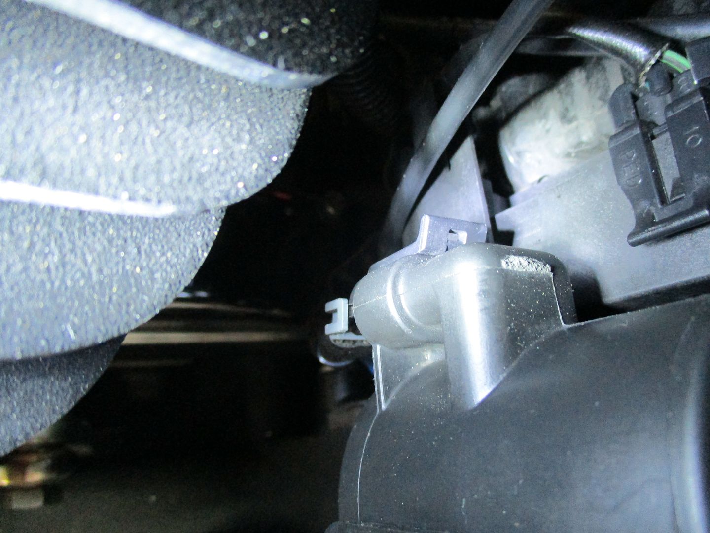
The connector attached to the coil pack-
The Delphi GT150 removed from coil-
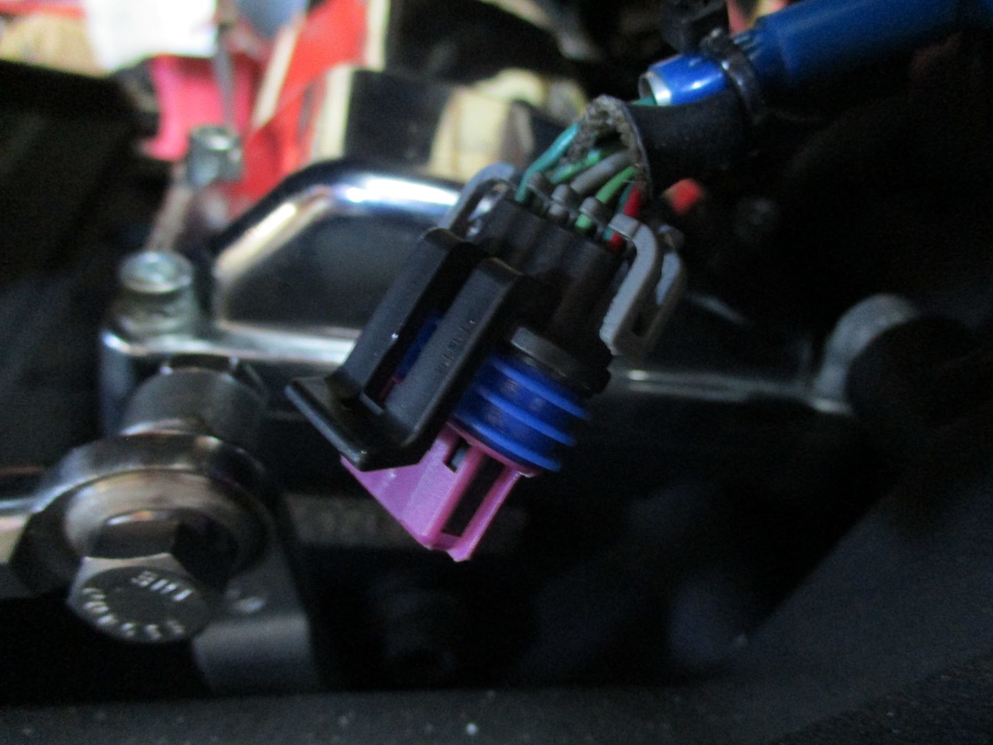
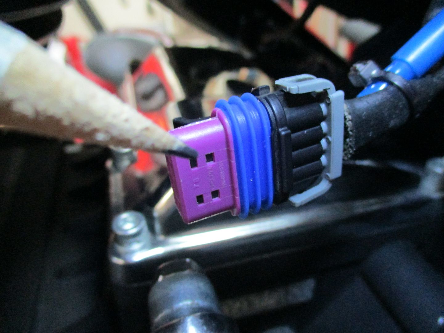
To open, remove the gray wire retainer/sealer at the rear of the connector by unlatching and sliding it out-
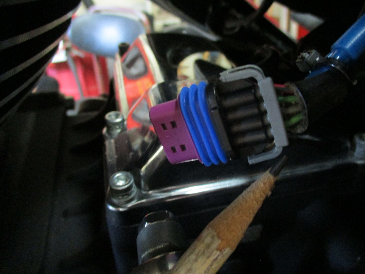
Then pry the purple piece at the front of the connector away from the accordion weather seal. It comes right off-
Next, slide the accordion seal away from the connector-
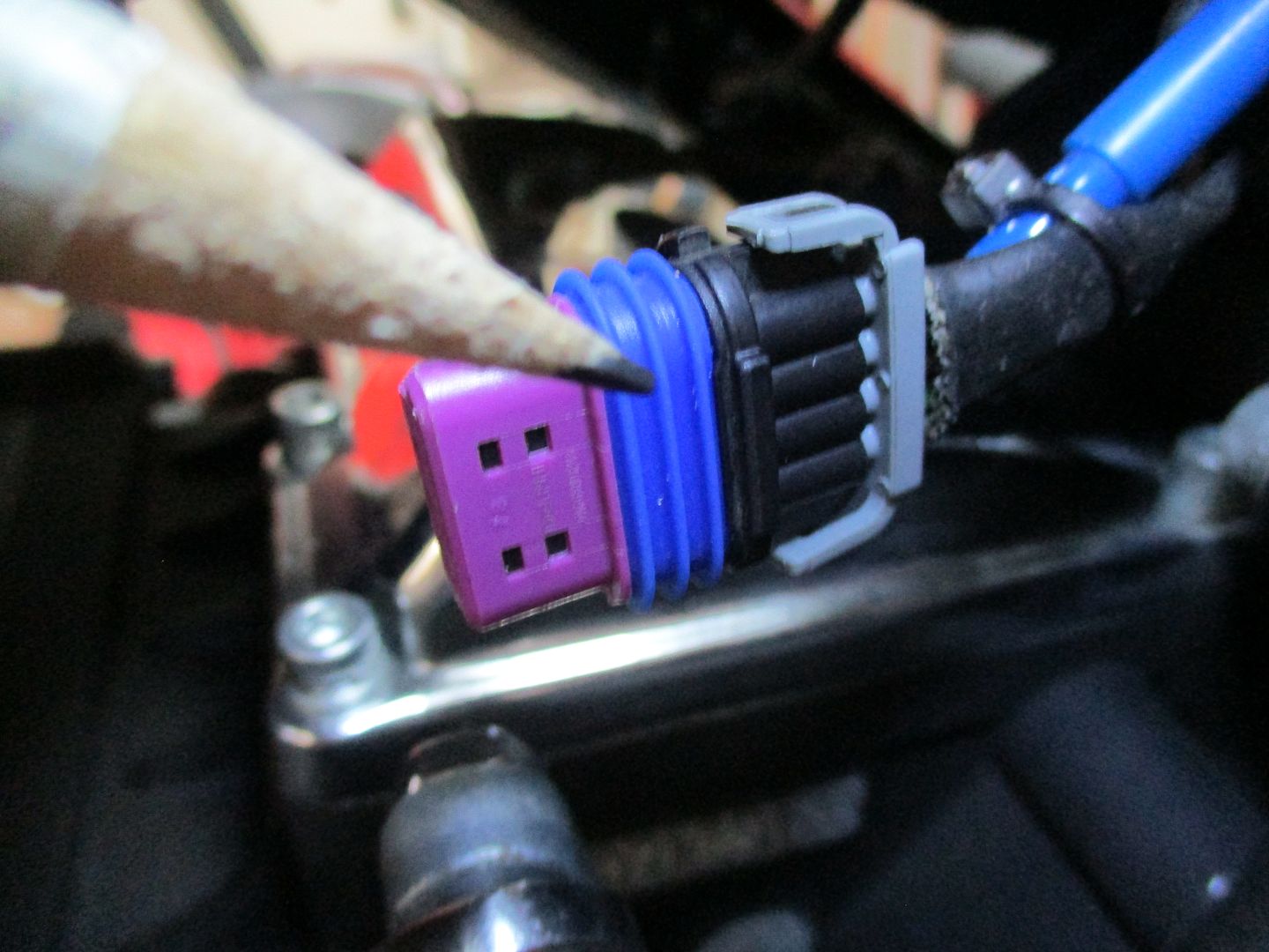
At this point you will have exposed the black plastic holding fingers that secure the metal terminals inside the connector. These are apparent in the exploded image showing the purple piece partially pulled out and the plastic fingers underneath. Gently pry up on the selected black finger above the selected terminal while pulling the selected wire rearward. Lifting the plastic locking finger will free the barb on the metal connector and allow the wire and terminal to be pulled out the back of the connector.
This will allow you better access for attaching an appropriate tap to that wire.
When finished, push the wire/terminal back into its hole from the rear until you hear it click and/or see the end protrude suitably.
Slide the accordion seal back over the front of the connector as well as the purple guide until it seats.
Lastly, reattach the rear gray wire retainer. Be sure to slide the portion molded to fit around the wires up inside the connector until the outside lock tabs engage on each side.
Ever wonder who designs this stuff?
Anyway, that's it. I'll try to post some better pics.
The main thing is that you get your tach pulse signal from the coil trigger wire.
Final note for Speedhut (and other) tachs. Put the tach setting at .5 pulse per revolution. All will work fine.
.
The coil on these models are basically a dual coil made into one with individual single firing to each cylinder. The coil assembly is attached with a 4-wire Delphi GT150 connector. There is a 12VDC power wire, an ION sensor wire, rear coil trigger, front coil trigger. The power wire is marked with a red stripe and on one end of the 4-wire row. I chose the front coil trigger wire that is at the opposite end of the 4-wire row at the connector.
All you have to do is somehow tap into this trigger wire and you'll have a suitable tach pulse.
You could be crude and just skin the insulation back, solder and tape.
I chose to open the Delphi connector and insert a piggy-back small solid wire into the metal connector terminal for the front cylinder trigger wire- opposite end from the power wire.
Opening this Delphi connector is very easy - if you know how to do it!
Exploded view of the Delphi GT150 H-D coil connector-

The connector attached to the coil pack-

The Delphi GT150 removed from coil-

To open, remove the gray wire retainer/sealer at the rear of the connector by unlatching and sliding it out-

Then pry the purple piece at the front of the connector away from the accordion weather seal. It comes right off-

Next, slide the accordion seal away from the connector-

At this point you will have exposed the black plastic holding fingers that secure the metal terminals inside the connector. These are apparent in the exploded image showing the purple piece partially pulled out and the plastic fingers underneath. Gently pry up on the selected black finger above the selected terminal while pulling the selected wire rearward. Lifting the plastic locking finger will free the barb on the metal connector and allow the wire and terminal to be pulled out the back of the connector.
This will allow you better access for attaching an appropriate tap to that wire.
When finished, push the wire/terminal back into its hole from the rear until you hear it click and/or see the end protrude suitably.
Slide the accordion seal back over the front of the connector as well as the purple guide until it seats.
Lastly, reattach the rear gray wire retainer. Be sure to slide the portion molded to fit around the wires up inside the connector until the outside lock tabs engage on each side.
Ever wonder who designs this stuff?
Anyway, that's it. I'll try to post some better pics.
The main thing is that you get your tach pulse signal from the coil trigger wire.
Final note for Speedhut (and other) tachs. Put the tach setting at .5 pulse per revolution. All will work fine.
.
Last edited by leafman60; Aug 14, 2016 at 12:51 PM.
Grand HDF Member
Joined: May 2008
Posts: 4,624
Likes: 189
From: Newcastle, Ca.
Nice write. I posted a tach install question yesterday in the Ignition/Tuner forum, no response yet. Maybe you can help. Here is the link and question:
Installing tach on 2011 RKC. Have read several threads and depending on the year, connection options change. The popular "pink" wire, pin 3 on ecm, does no exist on my bike. In fact, pin 3 on the ecm connector is plugged. That leaves me with pin 3 on the back of the speedometer or tapping into coils. I prefer to use pin 3, keeping everything under the dash and this tach signal should be cleaner. Apparently the speedo takes the serial data signal in at pin 2, then outputs a clean tach signal in pin 3. I bought the terminal pin and wired the tach up to pin 3 but tach still not responding. Can some one tell me what the voltage out is on pin 3 on the back of speedometer? I want to verify the signal before returning the tach.
https://www.hdforums.com/forum/ignit...-2011-rkc.html
Also, I did try the tach using a coil wire, tach did not respond. Maybe problem with tach. I would still like to verify tach voltage at speedo pin 3.
Thread Starter
|
Road Captain
Joined: Jun 2007
Posts: 632
Likes: 86
Nice write. I posted a tach install question yesterday in the Ignition/Tuner forum, no response yet. Maybe you can help. Here is the link and question:
Installing tach on 2011 RKC. Have read several threads and depending on the year, connection options change. The popular "pink" wire, pin 3 on ecm, does no exist on my bike. In fact, pin 3 on the ecm connector is plugged. That leaves me with pin 3 on the back of the speedometer or tapping into coils. I prefer to use pin 3, keeping everything under the dash and this tach signal should be cleaner. Apparently the speedo takes the serial data signal in at pin 2, then outputs a clean tach signal in pin 3. I bought the terminal pin and wired the tach up to pin 3 but tach still not responding. Can some one tell me what the voltage out is on pin 3 on the back of speedometer? I want to verify the signal before returning the tach.
https://www.hdforums.com/forum/ignit...-2011-rkc.html
Also, I did try the tach using a coil wire, tach did not respond. Maybe problem with tach. I would still like to verify tach voltage at speedo pin 3.
Installing tach on 2011 RKC. Have read several threads and depending on the year, connection options change. The popular "pink" wire, pin 3 on ecm, does no exist on my bike. In fact, pin 3 on the ecm connector is plugged. That leaves me with pin 3 on the back of the speedometer or tapping into coils. I prefer to use pin 3, keeping everything under the dash and this tach signal should be cleaner. Apparently the speedo takes the serial data signal in at pin 2, then outputs a clean tach signal in pin 3. I bought the terminal pin and wired the tach up to pin 3 but tach still not responding. Can some one tell me what the voltage out is on pin 3 on the back of speedometer? I want to verify the signal before returning the tach.
https://www.hdforums.com/forum/ignit...-2011-rkc.html
Also, I did try the tach using a coil wire, tach did not respond. Maybe problem with tach. I would still like to verify tach voltage at speedo pin 3.
2011 RK should be pre-Can Bus. If you have a plug in position #3 of the speedo connector, removing it and installing a proper terminal should make the tach work. I've done it several times.
The later Can Bus bikes are wired differently and do not have the vacant/plugged position #3.
Having said that, I would expect that you should also be able to draw a workable pulse signal off the coil if you get the correct coil wire. If you have the 4-wire connector on the coil, the opposite end should be one of the cylinder triggers.
Going to the #3 terminal is easy and clean. Should work.
.
Grand HDF Member
Joined: May 2008
Posts: 4,624
Likes: 189
From: Newcastle, Ca.
2011 RK should be pre-Can Bus. If you have a plug in position #3 of the speedo connector, removing it and installing a proper terminal should make the tach work. I've done it several times.
The later Can Bus bikes are wired differently and do not have the vacant/plugged position #3.
Having said that, I would expect that you should also be able to draw a workable pulse signal off the coil if you get the correct coil wire. If you have the 4-wire connector on the coil, the opposite end should be one of the cylinder triggers.
Going to the #3 terminal is easy and clean. Should work.
.
Thank you!! You confirmed everything I read and tried. I tried speedo pin 3 and off the coil, ylw/ble wire pin 53 off ecm.
I will try the coil wire once more. I poked through the ylw/ble coil wire cover when testing and 99% certain their was a connection. At least enough to see the tach move, erratically if not correctly. Making a hard wire tap connection like you may be worth a try. But, speedo pin 3 should work and its already wired now. A problem with tach always exists. Maybe I can test tach by wiring it to my car. Not sure, it maybe more difficult then wiring to my bike. No car schematics and everything is covered up...
Also, any idea what the voltage should be measured at speedo pin 3? I would like to verify if possible.
Thread Starter
|
Road Captain
Joined: Jun 2007
Posts: 632
Likes: 86
The voltage at #3 will be an intermittent voltage, a pulse, so it may be hard to measure with a volt meter. If your tach is good, it should work on #3.
Now, if this tach is not designed for a H-D, you will probably need to program it or set it to the proper firing order. Your 2011 is probably single fire so should be set for .5 fires per revolution.
Specifically, what tachometer are you trying to attach? That may be your problem.
Now, if this tach is not designed for a H-D, you will probably need to program it or set it to the proper firing order. Your 2011 is probably single fire so should be set for .5 fires per revolution.
Specifically, what tachometer are you trying to attach? That may be your problem.

6th Gear
Joined: May 2020
Posts: 10
Likes: 3
From: Houston
Hello Leafman,
I'm preparing to do this same operation, and wondered how you inserted/attached your jumper wire to the coil connector terminal? Did you open it and re-crimp or something else?
thanks,
Karlesto
I'm preparing to do this same operation, and wondered how you inserted/attached your jumper wire to the coil connector terminal? Did you open it and re-crimp or something else?
thanks,
Karlesto


Thread
Thread Starter
Forum
Replies
Last Post


