


iPod interface

Intermediate
Joined: Apr 2009
Posts: 31
Likes: 0
Ferromet, I copied the wiring diagram for the SESG2 at my dealer the other day and it shows the I-Pod connector to the 35 wire connector for the SESG2 application. Perhaps it will confirm that the wiring on your CVO Ultra is the same, or identify a difference between the two applications:
http://
In any case, thanks for taking the time for the review and installation information.
Carl
http://
In any case, thanks for taking the time for the review and installation information.
Carl
Stellar HDF Member


Joined: Mar 2007
Posts: 3,181
Likes: 686
From: Forest Hill, Md
Intermediate
Joined: Apr 2009
Posts: 31
Likes: 0
Ferromet, I copied the wiring diagram for the SESG2 at my dealer the other day and it shows the I-Pod connector to the 35 wire connector for the SESG2 application. Perhaps it will confirm that the wiring on your CVO Ultra is the same, or identify a difference between the two applications:
http://
In any case, thanks for taking the time for the review and installation information.
Carl
http://
In any case, thanks for taking the time for the review and installation information.
Carl
Kudos to Carl... thanks Man, that worked. So here's the deal, if you have a CVO bike with the Amp installed then the Tan/Blue and Violet/Gray wires need to be swapped... Tan/Blue should go into hole #31, Violet/Gray into hole #19.
Extreme HDF Member
Joined: Apr 2006
Posts: 10,449
Likes: 46
From: Roswell, GA
Ferromet, glad to help. Two small questions: pin-out 31 calls for TN/BK wire in the SESG2 wiring diagram, but in your reply you refer to a TN/BE (blue) wire; is the wire TN/ BK (black) or TN/BE (blue)? And did the instructions with the interface provide for different wiring locations than shown in the SESG2 wiring diagram?
Also, bikes with the 35-wire connector already on the bike (e.g. Ultras and non-Ultras that have added the non-Ultra overlay harness, p/n 70169-06 for CB, XM and/or HD's rear speaker kit) should be wired the same as the CVO bike with amplifier since the amplifier doesn't use the 35-wire connector--the amp simply takes the speaker outputs from the HK head unit via the speaker connection wires, amplifies them, and sends the amplified signal to speakers--in essence the amp is wired in series to the normal speaker outputs/wiring of a non-CVO Ultra.
As for the SESG2 wiring diagram, I copied it because I was interested in how the amplifier was wired to the HK head unit and the interface wiring was "just there" when I made the copy.
Carl
Intermediate
Joined: Apr 2009
Posts: 31
Likes: 0
Ferromet, glad to help. Two small questions: pin-out 31 calls for TN/BK wire in the SESG2 wiring diagram, but in your reply you refer to a TN/BE (blue) wire; is the wire TN/ BK (black) or TN/BE (blue)? And did the instructions with the interface provide for different wiring locations than shown in the SESG2 wiring diagram?
Also, bikes with the 35-wire connector already on the bike (e.g. Ultras and non-Ultras that have added the non-Ultra overlay harness, p/n 70169-06 for CB, XM and/or HD's rear speaker kit) should be wired the same as the CVO bike with amplifier since the amplifier doesn't use the 35-wire connector--the amp simply takes the speaker outputs from the HK head unit via the speaker connection wires, amplifies them, and sends the amplified signal to speakers--in essence the amp is wired in series to the normal speaker outputs/wiring of a non-CVO Ultra.
As for the SESG2 wiring diagram, I copied it because I was interested in how the amplifier was wired to the HK head unit and the interface wiring was "just there" when I made the copy.
Carl
Also, bikes with the 35-wire connector already on the bike (e.g. Ultras and non-Ultras that have added the non-Ultra overlay harness, p/n 70169-06 for CB, XM and/or HD's rear speaker kit) should be wired the same as the CVO bike with amplifier since the amplifier doesn't use the 35-wire connector--the amp simply takes the speaker outputs from the HK head unit via the speaker connection wires, amplifies them, and sends the amplified signal to speakers--in essence the amp is wired in series to the normal speaker outputs/wiring of a non-CVO Ultra.
As for the SESG2 wiring diagram, I copied it because I was interested in how the amplifier was wired to the HK head unit and the interface wiring was "just there" when I made the copy.
Carl
Carl,
There are 5 pins that come out of the new wiring harness that is supplied with the Ipod interface kit... Tan/Red, Tan/Blue, Violet/Gray, Red/Blue & Black/Blue. No more, no less.
First, here's what the instructions that come with the Ipod interface call for:
Pin Cavity 8 = Tan/Red, Pin Cavity 19 = Tan/Blue, Pin Cavity 31 = Violet/Gray... the instructions say that if you have the bluetooth module installed to take the Red/Blue and Black/Blue pins and individually wrap them with electrical tape. It goes on to say that if the bluetooth module is not installed to insert Red/Blue into Pin Cavity 4 and Black/Blue into Pin Cavity 27. I don't have the bluetooth so I did, in fact place these pins per the instructions. It should be noted that each of the pin cavities (8, 19, 31, 4, 27) are available with a dummy in them on my CVO Ultra.
This is what was shown on your sheet and what actually worked:
According to the sheet you provided Pin 8 = Tan/Red (same as instructions), Pin 13 = Yellow/Orange (already there, no change), Pin 14 = Yellow/Violet (already there, no change), Pin 19= Violet/Gray (Different than instructions), Pin 31 = Tan/Blk (there is no tan black)... the instruction sheet was kind of blurry so I assumed that this was calling for Tan/Blue into pin 31 so that is what I did and it worked.
Hope this makes sense.
Outstanding HDF Member
Joined: Apr 2009
Posts: 2,582
Likes: 2
From: Central Jersey
Here's another solution...send your radio to Iron Cross and have them install a ipod cable to your HD factory radio, the cable also charges your ipod. I paid $90.00 for it when I had my radio repaired by Iron Cross. Works great and you can extend the cable and have your ipod in your saddlebag.

Tourer
Joined: Dec 2007
Posts: 377
Likes: 2
Here's another solution...send your radio to Iron Cross and have them install a ipod cable to your HD factory radio, the cable also charges your ipod. I paid $90.00 for it when I had my radio repaired by Iron Cross. Works great and you can extend the cable and have your ipod in your saddlebag.
HD Forum Stories
The Best of Harley-Davidson for Lifelong Riders
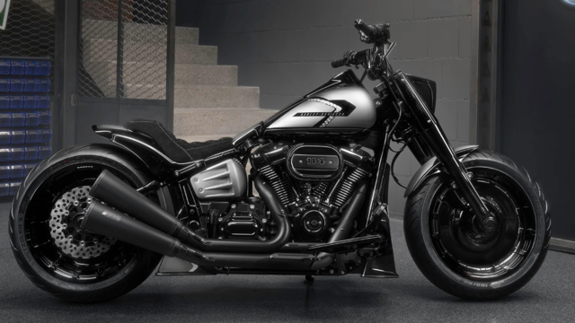
Harley-Davidson Fat Boy Becomes a Dark, Decepticon-Inspired Custom
Verdad Gallardo
6 Weirdest Harley-Davidsons Ever Sold to the Public
Verdad Gallardo
7 Times Harley-Davidson Chucked Tradition Out the Window
Verdad Gallardo
7 Surprising Harley-Davidson Products that Are Not Motorcycles
Verdad Gallardo
8 Best Harley-Davidson Motorcycles Ever
Pouria Savadkouei
10 Worst Harley-Davidson Motorcycles Ever
Pouria Savadkouei
Killer Custom's Jail Break Is The Breakout That Refused to Blend In
Verdad Gallardo
Crazy Bunderbike Build Looks Amazing, But Is It Impossible to Ride?
Verdad Gallardo
Harley-Davidson Reveals Super Cool Cafe Racer Concept
Verdad Gallardo


Tourer
Joined: Oct 2005
Posts: 353
Likes: 0
From:
Ferromet I should have posted what I was going through also on this forum. I just did it on the other forum. I did everything you did, what I ended up with was HD solution. They said on my 09 CVO was to reverse 19 to 31 and 31 to 19. My NIM harness wasn't,t working at all once I changed those wires the GPS worked, the iPod harness work with no problems.
Trey
Trey